pdf (2140k) - Adcon Engineering Co
pdf (2140k) - Adcon Engineering Co
pdf (2140k) - Adcon Engineering Co

You also want an ePaper? Increase the reach of your titles
YUMPU automatically turns print PDFs into web optimized ePapers that Google loves.
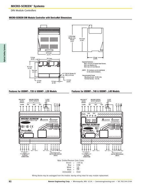
RLISTEDPresenceSensingDevice10Y8RRRLISTEDPresenceSensingDevice10Y8MICRO-SCREEN ® SystemsDIN Module <strong>Co</strong>ntrollersMICRO-SCREEN DIN Module <strong>Co</strong>ntroller with DeviceNet Dimensions4 FSD OutptModels only:128 mm(5.0")115.0 mm(4.53")Optical Safety Systems5.0 mm(0.20")81.0 mm(3.19")70.0 mm(2.76")5.5 mm(0.22")107.0 mm(4.21")97.0 mm(3.82")4.5 mm(0.18")Slot for Screws (2)M3.5 x 0.6 mm6.5 mm(0.26")Supplied Hardware:M3.5 0.6 mm (2) <strong>Co</strong>mbo Head ScrewsM3.5 mm Washers (2)M3.5 mm x 0.6 mm Nuts (2)(NOTE:81 mm(3.19")#6 hardware can be substitutedfor the metric hardware)Recommended TorqueMounting Screws: 16-20 in-lbsTerminal Screws: 5 in-lbsFeatures for USDINT-..T2D & USDINT-..L2D ModelsFeatures for USDINT-..T4D & USDINT-..L4D ModelsNON-SAFETYOUTPUTCONTACTMACHINE CONTROLOUTPUT CONTACTSALARM SSD FSD2 FSD1b a a b a b a bE-STOPSWITCHcadb+24 dc PEVdc COMNON-SAFETYOUTPUTCONTACTMACHINE CONTROLOUTPUT CONTACTSALARM SSD FSD2 FSD1b a a b a b a bE-STOPSWITCHcadb+24 dc PEVdc COM21 2224 2527 2830 3133 34 35 36 38 39 4021 2224 2527 2830 3133 34 35 36 38 39 40FSD2FSD1c d c dMICRO-SCREENMODEL NO. USDINT-xT2D or xL2DCAUTION WARNINGShock hazard may exist. For control reliableoperation always follow theinstructions in the manual.41 42 44 45CAUTIONShock hazard may exist.WARNINGFor control reliableoperation always follow theinstructions in the manual.C0466DeviceMAC ID ADDRESSBlocked or LatchedClearResetSTEADYLockoutBlankingAlignmentFLASHINGMICRO-SCREENMODEL NO. USDINT-xT4D or xL4DDeviceMAC ID ADDRESSCBlocked or LatchedClearResetSTEADYLockoutBlankingAlignmentFLASHINGDiagnostic Chart on Reverse Side0466Diagnostic Chart on Reverse SideD5 D4 D3 D2 D17 8 13 14 16 1718 19 20D5 D4 D3 D2 D17 8 13 14 16 1718 19 20V+V–CAN_H CAN_LSHIELDDEVICENETCONNECTIONSTEST 1TEST 2KEY 1KEY 2+12 COM T/R T/R DRAINVdcEMITTER AND RECEIVERCABLESV+V–CAN_H CAN_LSHIELDDEVICENETCONNECTIONSTEST 1TEST 2KEY 1KEY 2+12 COM T/R T/R DRAINVdcEMITTER AND RECEIVERCABLESNote: Emitter/Receiver <strong>Co</strong>lor <strong>Co</strong>desBrown = +12V dcBlue = COMWhite = T/RBlack = T/RUninsulated = DrainWiring blocks may be unplugged from the module, leaving wiring intact for easy module replacement.92 Banner <strong>Engineering</strong> <strong>Co</strong>rp. • Minneapolis, MN U.S.A. • bannerengineering.com • Tel: 763.544.3164