

ACTA TECHNICA CORVINIENSIS - Bulletin of Engineering
ACTA TECHNICA CORVINIENSIS - Bulletin of Engineering
ACTA TECHNICA CORVINIENSIS - Bulletin of Engineering
- No tags were found...

You also want an ePaper? Increase the reach of your titles
YUMPU automatically turns print PDFs into web optimized ePapers that Google loves.
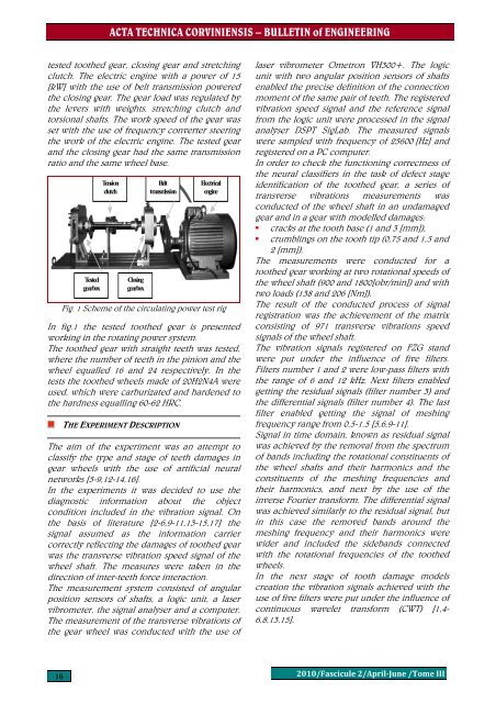
<strong>ACTA</strong> <strong>TECHNICA</strong> <strong>CORVINIENSIS</strong> – BULLETIN <strong>of</strong> ENGINEERINGtested toothed gear, closing gear and stretchingclutch. The electric engine with a power <strong>of</strong> 15[kW] with the use <strong>of</strong> belt transmission poweredthe closing gear. The gear load was regulated bythe levers with weights, stretching clutch andtorsional shafts. The work speed <strong>of</strong> the gear wasset with the use <strong>of</strong> frequency converter steeringthe work <strong>of</strong> the electric engine. The tested gearand the closing gear had the same transmissionratio and the same wheel base.TestedgearboxTensionclutchClosinggearboxBelttransmissionElectricalengineFig. 1 Scheme <strong>of</strong> the circulating power test rigIn fig.1 the tested toothed gear is presentedworking in the rotating power system.The toothed gear with straight teeth was tested,where the number <strong>of</strong> teeth in the pinion and thewheel equalled 16 and 24 respectively. In thetests the toothed wheels made <strong>of</strong> 20H2N4A wereused, which were carburizated and hardened tothe hardness equalling 60-62 HRC.THE EXPERIMENT DESCRIPTIONThe aim <strong>of</strong> the experiment was an attempt toclassify the type and stage <strong>of</strong> teeth damages ingear wheels with the use <strong>of</strong> artificial neuralnetworks [5-9,12-14,16].In the experiments it was decided to use thediagnostic information about the objectcondition included in the vibration signal. Onthe basis <strong>of</strong> literature [2-6,9-11,13-15,17] thesignal assumed as the information carriercorrectly reflecting the damages <strong>of</strong> toothed gearwas the transverse vibration speed signal <strong>of</strong> thewheel shaft. The measures were taken in thedirection <strong>of</strong> inter-teeth force interaction.The measurement system consisted <strong>of</strong> angularposition sensors <strong>of</strong> shafts, a logic unit, a laservibrometer, the signal analyser and a computer.The measurement <strong>of</strong> the transverse vibrations <strong>of</strong>the gear wheel was conducted with the use <strong>of</strong>laser vibrometer Ometron VH300+. The logicunit with two angular position sensors <strong>of</strong> shaftsenabled the precise definition <strong>of</strong> the connectionmoment <strong>of</strong> the same pair <strong>of</strong> teeth. The registeredvibration speed signal and the reference signalfrom the logic unit were processed in the signalanalyser DSPT SigLab. The measured signalswere sampled with frequency <strong>of</strong> 25600 [Hz] andregistered on a PC computer.In order to check the functioning correctness <strong>of</strong>the neural classifiers in the task <strong>of</strong> defect stageidentification <strong>of</strong> the toothed gear, a series <strong>of</strong>transverse vibrations measurements wasconducted <strong>of</strong> the wheel shaft in an undamagedgear and in a gear with modelled damages:• cracks at the tooth base (1 and 3 [mm]),• crumblings on the tooth tip (0,75 and 1,5 and2 [mm]).The measurements were conducted for atoothed gear working at two rotational speeds <strong>of</strong>the wheel shaft (900 and 1800[obr/min]) and withtwo loads (138 and 206 [Nm]).The result <strong>of</strong> the conducted process <strong>of</strong> signalregistration was the achievement <strong>of</strong> the matrixconsisting <strong>of</strong> 971 transverse vibrations speedsignals <strong>of</strong> the wheel shaft.The vibration signals registered on FZG standwere put under the influence <strong>of</strong> five filters.Filters number 1 and 2 were low-pass filters withthe range <strong>of</strong> 6 and 12 kHz. Next filters enabledgetting the residual signals (filter number 3) andthe differential signals (filter number 4). The lastfilter enabled getting the signal <strong>of</strong> meshingfrequency range from 0.5-1.5 [5,6,9-11].Signal in time domain, known as residual signalwas achieved by the removal from the spectrum<strong>of</strong> bands including the rotational constituents <strong>of</strong>the wheel shafts and their harmonics and theconstituents <strong>of</strong> the meshing frequencies andtheir harmonics, and next by the use <strong>of</strong> theinverse Fourier transform. The differential signalwas achieved similarly to the residual signal, butin this case the removed bands around themeshing frequency and their harmonics werewider and included the sidebands connectedwith the rotational frequencies <strong>of</strong> the toothedwheels.In the next stage <strong>of</strong> tooth damage modelscreation the vibration signals achieved with theuse <strong>of</strong> five filters were put under the influence <strong>of</strong>continuous wavelet transform (CWT) [1,4-6,8,13,15].162010/Fascicule 2/AprilJune /Tome III


