- Page 1 and 2:
Dolphin ® 9700 Mobile Computerswit
- Page 3 and 4:
Table of ContentsChapter 1 - Agency
- Page 5 and 6:
System Menu........................
- Page 7 and 8:
Communicating with the Dolphin Term
- Page 9 and 10:
1Agency InformationDolphin 9700 mob
- Page 11 and 12:
R&TTE Compliance Statement—802.11
- Page 13 and 14:
2Getting StartedOut of the BoxVerif
- Page 15 and 16:
Step 4. Set the Time and DateOn the
- Page 17 and 18:
Icons in the Navigation BarIndicato
- Page 19 and 20:
To move an icon to the top of the S
- Page 21 and 22:
3Hardware OverviewStandard Configur
- Page 23 and 24:
Accessories for the 9700Each of the
- Page 25 and 26:
Front Panel Features for the 9700Bl
- Page 27 and 28:
Back Panel Features for the 9700Bat
- Page 29 and 30:
Installing a Memory Card1. Press th
- Page 31 and 32:
Using the Touch PanelHoneywell defi
- Page 33 and 34:
BatteriesThere are two types of bat
- Page 35 and 36:
The default values for these entrie
- Page 37 and 38:
4Using the Scan Image EngineOvervie
- Page 39 and 40:
DecodingThe terminal supports two t
- Page 41 and 42:
Capturing ImagesThe image-capture p
- Page 43 and 44:
5Using the Color CameraOverviewAll
- Page 45 and 46:
MenuTap Menu on the Command Bar to
- Page 47 and 48:
6Using the KeyboardsAvailable Keybo
- Page 49 and 50:
Using the Modifier KeysName Key Fun
- Page 51 and 52:
Key Normal Shift Blue Shift-Blue Bl
- Page 53 and 54:
Key Normal Shift Blue Blue-Lock Red
- Page 55 and 56:
7System SettingsOverviewCustomized
- Page 57 and 58:
Personal MenuTo access the Personal
- Page 59 and 60:
Additional FunctionsThe Assign a pr
- Page 61 and 62:
5. Right-click on an empty area and
- Page 63 and 64:
BacklightThe Backlight system setti
- Page 65 and 66:
External GPSExternal GPS determines
- Page 67 and 68:
RILThe RIL Information screen displ
- Page 69 and 70:
1. Tap Remove Programs. In the list
- Page 71 and 72:
Task ManagerThe Task Manager provid
- Page 73 and 74: 8CommunicationConnections MenuThe C
- Page 75 and 76: 5. When the IrDA port finds the ali
- Page 77 and 78: *Proxy Server ConnectionsIf you are
- Page 79 and 80: 4. When the radio is activated (i.e
- Page 81 and 82: Setting Up the Host WorkstationVeri
- Page 83 and 84: • If you want the program to be p
- Page 85 and 86: 9Working with GSM/HSDPA/UMTS/GPRS/E
- Page 87 and 88: Installing a SIM Card1. Press the P
- Page 89 and 90: Volume ControlUse the Dolphin keybo
- Page 91 and 92: Setup OptionsTap Menu > Options.The
- Page 93 and 94: 4. Enter the Access point name. Tap
- Page 95 and 96: Manual Network SelectionYou can sel
- Page 97 and 98: 10Working with the Bluetooth RadioE
- Page 99 and 100: 4. You are prompted to enter a pass
- Page 101 and 102: Types of Devices and ServicesWhen y
- Page 103 and 104: Transferring Files1. Tap Start > Fi
- Page 105 and 106: 11Working with GPSOverviewThe Dolph
- Page 107 and 108: 12Dolphin 9700 HomeBase DeviceOverv
- Page 109 and 110: COMM LEDThis is the communication L
- Page 111 and 112: Serial ConnectorThe following diagr
- Page 113 and 114: CommunicationUSBDolphin terminals s
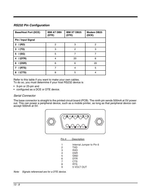
- Page 115 and 116: RS232 Pin ConfigurationBase /Host P
- Page 117 and 118: 13Dolphin 9700 Mobile Base DeviceOv
- Page 119 and 120: Bottom PanelThe power supply and RS
- Page 121 and 122: MountingThe adjustable mounting bra
- Page 123: Establishing CommunicationThe RS232
- Page 127 and 128: Power SupplyThe base includes a pow
- Page 129 and 130: MountingThis base should be mounted
- Page 131 and 132: 15Dolphin 9700 QuadCharger DeviceOv
- Page 133 and 134: Supplying PowerThe charger must be
- Page 135 and 136: TroubleshootingIf you encounter pro
- Page 137 and 138: 16Customer SupportProduct Service a
- Page 139 and 140: Limited WarrantyHoneywell Internati
- Page 142: Honeywell Scanning & Mobility9680 O