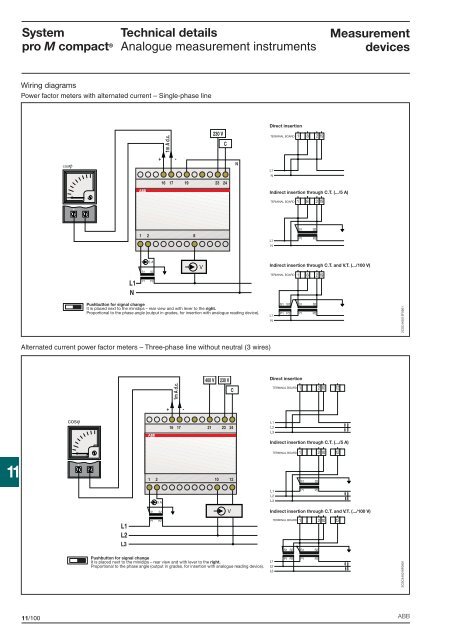
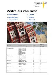
<strong>System</strong><strong>pro</strong> M compact ®<strong>Technical</strong> <strong>details</strong>Analogue measurement instrumentsMeasurementdevicesWiring diagramsPower factor meters with alternated current – Single-phase line1m A d.c.230 VCDirect insertionTERMINAL BOARD18 219cosϕ+ -NL1N16 17 1923 240+Indirect insertion through C.T. (.../5 A)TERMINAL BOARD1 8 2 191 2 8L1NS1P1S2P2L1NS1P15 AS2P2VIndirect insertion through C.T. and V.T. (.../100 V)TERMINAL BOARD1 8 219Pushbutton for signal changeIt is placed next to the minidips – rear view and with lever to the right.Proportional to the phase angle (output in grades, for insertion with analogue reading device).L1NS1 S2P1 P2S1P1S2P22CSC445015F0901Alternated current power factor meters – Three-phase line without neutral (3 wires)1m A d.c.+ -400 V 230 VCDirect insertionTERMINAL BOARD 1 210 12cosϕ16 1721 23 24L1L2L3Indirect insertion through C.T. (.../5 A)0TERMINAL BOARD 1 210 1211+1 2 10 12S1S2L1L2L3S1P15 AS2P2Pushbutton for signal changeIt is placed next to the minidips – rear view and with lever to the right.Proportional to the phase angle (output in grades, for insertion with analogue reading device).VL1L2L3P1P2Indirect insertion through C.T. and V.T. (.../100 V)TERMINAL BOARD 1 210 12L1L2L3S1 S2P1 P2S1P1S2P22CSC445016F090111/100 ABB
<strong>System</strong><strong>pro</strong> M compact ®<strong>Technical</strong> <strong>details</strong>Digital measurement instrumentsMeasurementdevicesDMTME MULTIMETER Display L1, L2, L3 for the visualisation of the electrical parameters of every phase, of the energycounters and the time counters. The lighting point, on the right of the third display digits (L3), fl ashesduring RS485 communication (only for DMTME-I-485 model) 4-th display for the visualisation of the electrical parameters of the three-phase system Key for the scan of the electrical parameters for each phase and the energy counters, visualisedon the displays L1, L2, L3 (), if you press-and-hold-down the previous page will be displayed Key for the scan of the three-phase electrical parameters, visualised on the 4-th display () andthe time counters, if you press-and-hold-down the previous page will be displayed 9 LEDs for the indication of the electrical parameters displayed on the three displays L1, L2, L3() 7 LEDs for the indication of the electrical parameters displayed on the 4-th display () Key for set out the visualisation of maximum values of the electrical parameters (LED MAX switched on), of minimum values (LED MIN switched on ) and average values (calculation periodof 15 minutes) (AVERAGE, simultaneously LED MIN and MAX switched on). When the LED, whichshows the selected type of visualisation, is switched on, it will be possible to scan in sequence thedifferent electrical parameters by pressing and keys LED for the identifi cation of the visualised electrical parameters scale on both instrument’s displays and (factor K = kilo, parameter x 1.000 and factor M = mega, parameter x 1.000.000) LED for the identifi cation of the max/min/average values displayed on the displays and + Press together allow the access to the confi guration menu (setup)11Measured parametersPhase-to-phase voltage (VL-L)Line and three-phase voltage (VL-N and ΣV)Line and three-phase current (A and ΣA)FrequencyLine and three-phase active power (W and ΣW)Line and three-phase reactive power (VAr and ΣVAr)Line and three-phase apparent power (VA and ΣVA)Line and three-phase power-factor/cosj, with indication of theconventional sign (+ = inductive load, - = capacitive load)VL1-L2, VL2-L3, VL3-L1VL1-N, VL2-N, VL3-N, ΣVI1, I2, I3, ΣIHzW1, W2, W3, ΣWVAr1, VAr2, VAr3, ΣVArVA1, VA2, VA3, ΣVAPF1, PF2, PF3, ΣPFABB11/101