Technical details System pro M compact®
Technical details System pro M compact®
Technical details System pro M compact®
- No tags were found...

You also want an ePaper? Increase the reach of your titles
YUMPU automatically turns print PDFs into web optimized ePapers that Google loves.
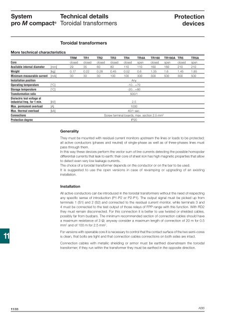
<strong>System</strong><strong>pro</strong> M compact ®<strong>Technical</strong> <strong>details</strong>Toroidal transformersProtectiondevicesToroidal transformersMore technical characteristicsTRM TR1 TR2 TR3 TR4 TR4A TR160 TR160A TR5 TR5ACore closed closed closed closed closed open closed open closed openAvailable internal diameter [mm] 29 35 60 80 110 110 160 160 210 210Weight [kg] 0.17 0.22 0.28 0.45 0.52 0.6 1.35 1.6 1.45 1.85Minimum measurable current [mA] 30 30 30 100 100 300 300 500 300 500Installation positionAnyOperating temperature [°C] -10…+70Storage temperature [°C] -20…+80Transformation ratio 500/1Dielectric test voltage atindustrial freq. for 1 min. [kV] 2.5Max. permanent overload [A] 1000Max. thermal overload [kA] 40/1 sec.Connections Screw terminal boards, max. section 2.5 mm 2Protection degreeIP20GeneralityThey must be mounted with residual current monitors upstream the lines or loads to be <strong>pro</strong>tected;all active conductors (phases and neutral) of single-phase as well as of three-phases lines mustpass through them.In this way these devices perform the vector sum of line currents detecting the possible homopolardifferential currents that leak to earth: their core of sheet iron has high magnetic <strong>pro</strong>perties that allowto detect even very low leakage currents.The choice of a toroidal transformer depends on the conductor or on the bar to be used.It is suggested to use the open versions in case of revamping or upgrading of an existinginstallation.InstallationAll active conductors can be introduced in the toroidal transformers without the need of respectingany specifi c sense of introduction (P1-P2 or P2-P1). The output signal must be picked up fromterminals 1 (S1) and 2 (S2) and connected to the residual current monitor, while terminals 3 and4 must be connected to the test output of those relays of FPP range with this function. With RD2they must remain disconnected. For this connection it is better to use twisted or shielded cables,possibly far from busbars. The minimum recommended section of connection cables should havea maximum resistance of 3 Ω; anyway consider a maximum length of connection of 20 m for 0.5mm 2 and of 100 m for 2.5 mm 2 .11For versions with openable core it is necessary to control that the contact surface of the two semi-coresis clean, that bolts are tight and that connection cables connections on both sides are intact.Connection cables with metallic shielding or armor must be earthed downstream the toroidaltransformer; if they run within the transformer they must be earthed in the opposite direction.11/88 ABB