Technical details System pro M compact®
Technical details System pro M compact®
Technical details System pro M compact®
- No tags were found...

Create successful ePaper yourself
Turn your PDF publications into a flip-book with our unique Google optimized e-Paper software.
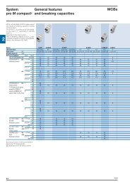
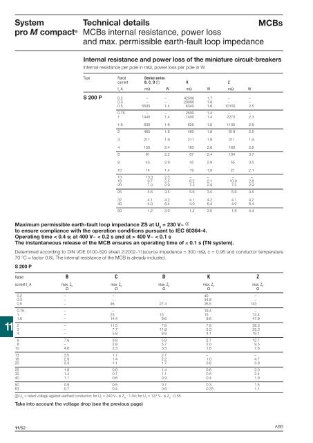
<strong>System</strong><strong>pro</strong> M compact ®<strong>Technical</strong> <strong>details</strong>MCBsMCBs internal resistance, power lossand max. permissible earth-fault loop impedanceInternal resistance and power loss of the miniature circuit-breakersInternal resistance per pole in mΩ, power loss per pole in WType Rated Device seriescurrent B, C, D K ZI nA mΩ W mΩ W mΩ WS 200 P 0.2 – – 42500 1.7 – –0.3 – – 20000 1.8 – –0.5 5500 1.4 6340 1.6 10100 2.50.75 – – 2500 1.4 – –1 1440 1.4 1400 1.4 2270 2.31.6 630 1.6 625 1.6 1100 2.82 460 1.8 460 1.8 619 2.53 211 1.9 211 1.9 211 1.94 150 2.4 163 2.6 163 2.66 61 2.2 67 2.4 104 3.78 45 2.9 45 2.9 55 3.510 14 1.4 19 1.9 21 2.113 13.3 2.3 – – – –16 9.7 2.5 8.2 2.1 10.9 2.820 7.3 2.9 7.3 2.9 7.3 2.925 5.6 3.5 5.6 3.5 5.6 3.532 4.1 4.2 4.1 4.2 4.1 4.240 4.0 6.4 4.0 6.4 4.0 6.450 1.2 3.0 1.2 3.0 1.8 4.4Maximum permissible earth-fault loop impedance ZS at U 0= 230 V~ to ensure compliance with the operation conditions pursuant to IEC 60364-4.Operating time < 0.4 s; at 400 V~ < 0.2 s and at > 400 V~ < 0.1 sThe instantaneous release of the MCB ensures an operating time of ≤ 0.1 s (TN system).Determined according to DIN VDE 0100-520 sheet 2:2002-11(source impedance = 300 mΩ, c = 0.95 and conductor temperature70 °C = factor 0.8). The internal resistance of the MCB is already included.S 200 PRated B C D K Z11current I nA max. Z Smax. Z Smax. Z Smax. Z Smax. Z S 0.2 – – 40 –0.3 – – 34.8 –0.5 – 46 27.4 26.5 1430.75 – – 19.4 –1 – 23 15 15 74.41.6 – 14.4 9.6 9.6 47.92 – 11.5 7.8 7.8 38.33 – 7.7 11.8 5.3 25.34 – 5.8 8.8 4.1 19.16 7.6 3.8 5.9 2.7 12.78 – 2.8 5.7 2.0 9.510 4.6 2.3 3.5 1.6 7.613 3.5 1.7 2.7 – –16 2.9 1.4 2.2 1.0 4.720 2.3 1.1 1.7 0.8 3.825 1.8 0.9 1.4 0.6 3.032 1.4 0.7 1.1 0.5 2.440 1.1 0.6 0.9 0.4 1.950 0.9 0.5 0.7 0.3 1.563 0.7 0.4 0.6 0.25 1.1 U 0= rated voltage against earthed conductor; for U 0= 240 V~ is Z S· 1.04; for U 0= 127 V~ is Z S· 0.55Take into account the voltage drop (see the previous page)11/52 ABB