Technical details System pro M compact®
Technical details System pro M compact®
Technical details System pro M compact®
- No tags were found...

You also want an ePaper? Increase the reach of your titles
YUMPU automatically turns print PDFs into web optimized ePapers that Google loves.
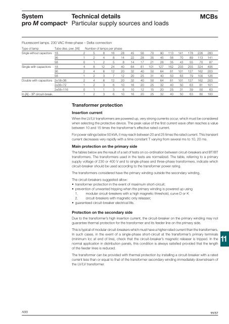
<strong>System</strong><strong>pro</strong> M compact ®<strong>Technical</strong> <strong>details</strong>Particular supply sources and loadsMCBsFluorescent lamps. 230 VAC three-phase – Delta connectionType of lamp Tube diss. pwr. [W] Number of lamps per phaseSingle without capacitors 18 2 5 8 16 28 45 56 70 90 113 141 178 226 28336 1 2 4 8 14 22 28 35 45 56 70 89 113 14158 0 1 2 5 8 14 17 21 28 35 43 55 70 87Single with capacitors 18 4 8 12 24 40 64 81 101 127 162 203 255 324 40636 2 4 6 12 20 32 40 50 64 81 101 127 162 20358 1 2 3 7 12 20 25 31 40 50 63 79 100 126Double with capacitors 2x18=36 2 4 6 12 20 32 40 50 64 81 101 127 162 2032x36=72 1 2 3 6 10 16 20 25 32 40 50 63 81 1012x58=116 0 1 1 3 6 10 12 15 20 25 31 39 50 63In [A] - 3P circuit-break. 1 2 3 6 10 16 20 25 32 40 50 63 80 100Transformer <strong>pro</strong>tectionInsertion currentWhen the LV/LV transformers are powered up, very strong currents occur, which must be consideredwhen selecting the <strong>pro</strong>tective device. The peak value of the fi rst current wave often reaches a valuebetween 10 and 15 times the transformer’s effective rated current.For power ratings below 50 kVA, it may reach between 20 and 25 times the rated current. This transientcurrent decreases very rapidly with a time constant T varying from several ms to 10, 20 ms.Main <strong>pro</strong>tection on the primary sideThe tables below are the result of a set of tests on co-ordination between circuit-breakers and BT/BTtransformers. The transformers used in the tests are normalized. The table, referring to a primarysupply voltage of 230 or 400 V and to single-phase and three-phase transformers, indicate whichcircuit-breaker should be used according to the transformer power rating.The transformers considered have the primary winding outside the secondary winding.The circuit-breakers suggested allow:• transformer <strong>pro</strong>tection in the event of maximum short-circuit;• prevention of unwanted tripping when the primary winding is powered up using1. modular circuit-breakers with a high magnetic threshold, curve D or K2. circuit-breakers with magnetic only releaser;• guaranteed circuit-breaker electrical life.Protection on the secondary sideDue to the transformer’s high insertion current, the circuit-breaker on the primary winding may notguarantee thermal <strong>pro</strong>tection for the transformer and its feeder line on the primary side.This is typical of modular circuit-breakers which must have a higher rated current than the transformers.In such cases, in the event of a single-phase short-circuit at the transformer’s primary terminals(minimum Icc at end of line), check that the circuit-breaker’s magnetic releaser is tripped. In thenormal application in distribution panels, this condition is always satisfi ed <strong>pro</strong>vided that the lengthof the feeder lines is reduced.The transformer can be <strong>pro</strong>vided with thermal <strong>pro</strong>tection by installing a circuit-breaker with a ratedcurrent less than or equal to that of the transformer secondary winding immediately downstream ofthe LV/LV transformer.11ABB11/57