Technical details System pro M compact®
Technical details System pro M compact®
Technical details System pro M compact®
- No tags were found...

Create successful ePaper yourself
Turn your PDF publications into a flip-book with our unique Google optimized e-Paper software.
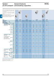
<strong>System</strong><strong>pro</strong> M compact ®<strong>Technical</strong> <strong>details</strong>Max./min. current/voltageammetric and voltmetric relaysLoadmanagementdevicesExample of MINIMUM VOLTAGE relay (RLV) operating principleManaging a load with the following markingI n= 5 A (standard operation rated current)V n= 230 V a.c. (standard operation rated voltage)V min= 200 V a.c. (RLV relay intervention)1. Connect according to the diagram (as V min=200 V).FNetwork to be measured V min 200 V a.c. LOADNC2. Set the “Voltage %” trimmer to 66.7%, as:200 (V min.)V% = x100=66.7%300 (V set)being the terminal 7-11 wired.3. Set the “Hysteresis %” trimmer; choosing 10% you get an interventionrange from 200 to 220 V (200+10%=220 V).The relay intervention will be 200 V and the return to the standardoperation 220 V.4. Set the “Delay” trimmer. This allows to delay the relay interventiontime (1…30 sec).During the delay the “Power ON” LED blinks. At the end of the delaythe “Alarm” LED is permanently lighted and the relay intervenes.7 8 9 10 11 12A1 2 3 4 5 6Supplyvoltage230 V a.c.RLVAlarmNOTEGenerally connect terminals:7-10 if V minis ≤100 V7-11 if V minis >100 V and ≤300 V7-12 if V minis >300 V and ≤500 VVn=230 V220 VVmin=200 VAlarm onRegularoperationSelectedhysteresis window=10%Alarm off as out of thehysteresis windowAlarm on as within of thehysteresis windowExample of MAXIMUM VOLTAGE relay (RHV) operating principle11Managing a load with the following markingI n= 5 A (standard operation rated current)V n= 230 V a.c. (standard operation rated voltage)V max= 250 V a.c. (RHV relay intervention)1. Connect according to the diagram (as V max=250 V).FNC7 8 9 10 11 12Network to be measured V max 250 V a.c.LOAD2. Set the “Voltage%” trimmer to 83.33%, as:250 (VV% = max)x100=83.33%300 (V set)being terminal 7-11 wired.3. Set the “Hysteresis %” trimmer; choosing 5% you get an interventionrange from 237.5 to 250 V (250-5%=237.5 V).The relay intervention will be 250 V and the return to the standardoperation 237.5 V.4. Set the “Delay” trimmer. This allows to delay the relay interventiontime (1…30 sec).During the delay the “Power ON” LED blinks; at the end of the delaythe “Alarm” LED is permanently lighted and the relay intervenes.A1 2 3 4 5 6Supplyvoltage230 V a.c.RHVAlarmNOTEGenerally connect terminals:7-10 if V maxis ≤100 V7-11 if V maxis >100 V and ≤300 V7-12 if V maxis >300 V and ≤500 VVmax=250 V237.5 VVn=230 VAlarm onRegularoperationSelectedhysteresis window=5%Alarm off as out of thehysteresis windowAlarm on as within of thehysteresis window11/98 ABB