Technical details System pro M compact®
Technical details System pro M compact®
Technical details System pro M compact®
- No tags were found...

Create successful ePaper yourself
Turn your PDF publications into a flip-book with our unique Google optimized e-Paper software.
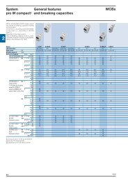
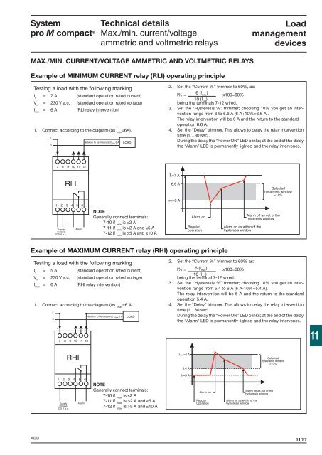
<strong>System</strong><strong>pro</strong> M compact ®<strong>Technical</strong> <strong>details</strong>Max./min. current/voltageammetric and voltmetric relaysLoadmanagementdevicesMAX./MIN. CURRENT/VOLTAGE AMMETRIC AND VOLTMETRIC RELAYSExample of MINIMUM CURRENT relay (RLI) operating principleTesting a load with the following markingI n= 7 A (standard operation rated current)V n= 230 V a.c. (standard operation rated voltage)I min= 6 A (RLI relay intervention)1. Connect according to the diagram (as I min=6A).FNetwork to be measured I min 6 A LOADN2. Set the “Current %” trimmer to 60%, as:l% =6 (l min.)x100=60%10 (l set)being the terminals 7-12 wired.3. Set the “Hysteresis %” trimmer; choosing 10% you get an interventionrange from 6 to 6.6 A (6 A+10%=6.6 A).The relay intervention will be 6 A and the return to the standardoperation 6.6 A.4. Set the “Delay” trimmer. This allows to delay the relay interventiontime (1…30 sec).During the delay the “Power ON” LED blinks; at the end of the delaythe “Alarm” LED is permanently lighted and the relay intervenes.C7 8 9 10 11 12A1 2 3 4 5 6Supplyvoltage230 V a.c.RLIAlarmNOTEGenerally connect terminals:7-10 if l minis ≤2 A7-11 if l minis >2 A and ≤5 A7-12 if l minis >5 A and ≤10 AIn=7 A6.6 AImin=6 AAlarm onRegularoperationSelectedhysteresis window=10%Alarm off as out of thehysteresis windowAlarm on as within of thehysteresis windowExample of MAXIMUM CURRENT relay (RHI) operating principleTesting a load with the following markingI n= 5 A (standard operation rated current)V n= 230 V a.c. (standard operation rated voltage)I max= 6 A (RHI relay intervention)1. Connect according to the diagram (as I max=6 A).FNC7 8 9 10 11 12Network to be measured I max 6 ALOAD2. Set the “Current %” trimmer to 60% as:l% = 6 (l max) x100=60%10 (lbeing the terminal set)7-12 wired.3. Set the “Hysteresis %” trimmer; choosing 10% you get an interventionrange from 5.4 to 6 A (6 A-10%=5.4 A).The relay intervention will be 6 A and the return to the standardoperation 5.4 A.4. Set the “Delay” trimmer. This allows to delay the relay interventiontime (1…30 sec).During the delay the “Power ON” LED blinks; at the end of the delaythe “Alarm” LED is permanently lighted and the relay intervenes.11A1 2 3 4 5 6Supplyvoltage230 V a.c.RHIAlarmNOTEGenerally connect terminals:7-10 if l maxis ≤2 A7-11 if l maxis >2 A and ≤5 A7-12 if l maxis >5 A and ≤10 AImax=6 A5.4 AIn=5 AAlarm onRegularOperationSelectedhysteresis window=10%Alarm off as out of thehysteresis windowAlarm on as within of thehysteresis windowABB11/97