Technical details System pro M compact®
Technical details System pro M compact®
Technical details System pro M compact®
- No tags were found...

You also want an ePaper? Increase the reach of your titles
YUMPU automatically turns print PDFs into web optimized ePapers that Google loves.
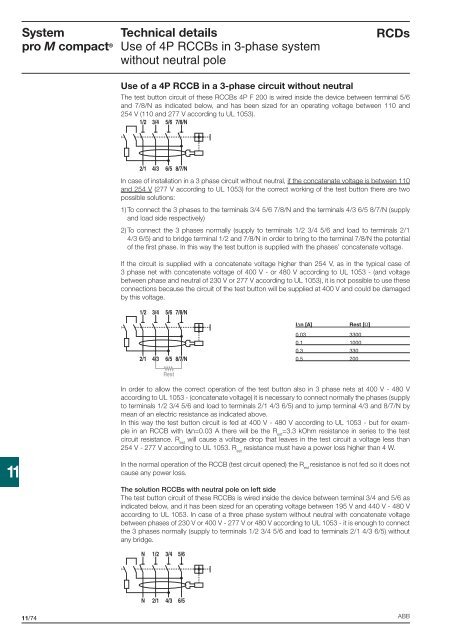
<strong>System</strong><strong>pro</strong> M compact ®<strong>Technical</strong> <strong>details</strong>Use of 4P RCCBs in 3-phase systemwithout neutral poleRCDsUse of a 4P RCCB in a 3-phase circuit without neutralThe test button circuit of these RCCBs 4P F 200 is wired inside the device between terminal 5/6and 7/8/N as indicated below, and has been sized for an operating voltage between 110 and254 V (110 and 277 V according tu UL 1053).1/2 3/4 5/6 7/8/N2/1 4/36/5 8/7/NIn case of installation in a 3 phase circuit without neutral, if the concatenate voltage is between 110and 254 V (277 V according to UL 1053) for the correct working of the test button there are twopossible solutions:1) To connect the 3 phases to the terminals 3/4 5/6 7/8/N and the terminals 4/3 6/5 8/7/N (supplyand load side respectively)2) To connect the 3 phases normally (supply to terminals 1/2 3/4 5/6 and load to terminals 2/14/3 6/5) and to bridge terminal 1/2 and 7/8/N in order to bring to the terminal 7/8/N the potentialof the fi rst phase. In this way the test button is supplied with the phases’ concatenate voltage.If the circuit is supplied with a concatenate voltage higher than 254 V, as in the typical case of3 phase net with concatenate voltage of 400 V - or 480 V according to UL 1053 - (and voltagebetween phase and neutral of 230 V or 277 V according to UL 1053), it is not possible to use theseconnections because the circuit of the test button will be supplied at 400 V and could be damagedby this voltage.1/2 3/45/67/8/NIΔn [A]Rest [Ω]0.03 33000.1 10000.3 3300.5 2002/1 4/36/58/7/NRestIn order to allow the correct operation of the test button also in 3 phase nets at 400 V - 480 Vaccording to UL 1053 - (concatenate voltage) it is necessary to connect normally the phases (supplyto terminals 1/2 3/4 5/6 and load to terminals 2/1 4/3 6/5) and to jump terminal 4/3 and 8/7/N bymean of an electric resistance as indicated above.In this way the test button circuit is fed at 400 V - 480 V according to UL 1053 - but for examplein an RCCB with IΔn=0.03 A there will be the R est=3.3 kOhm resistance in series to the testcircuit resistance. R estwill cause a voltage drop that leaves in the test circuit a voltage less than254 V - 277 V according to UL 1053. R estresistance must have a power loss higher than 4 W.11In the normal operation of the RCCB (test circuit opened) the R estresistance is not fed so it does notcause any power loss.The solution RCCBs with neutral pole on left sideThe test button circuit of these RCCBs is wired inside the device between terminal 3/4 and 5/6 asindicated below, and it has been sized for an operating voltage between 195 V and 440 V - 480 Vaccording to UL 1053. In case of a three phase system without neutral with concatenate voltagebetween phases of 230 V or 400 V - 277 V or 480 V according to UL 1053 - it is enough to connectthe 3 phases normally (supply to terminals 1/2 3/4 5/6 and load to terminals 2/1 4/3 6/5) withoutany bridge.N 1/23/45/6N 2/14/36/511/74 ABB