Technical details System pro M compact®
Technical details System pro M compact®
Technical details System pro M compact®
- No tags were found...

Create successful ePaper yourself
Turn your PDF publications into a flip-book with our unique Google optimized e-Paper software.
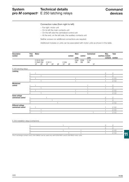
<strong>System</strong><strong>pro</strong> M compact ®<strong>Technical</strong> <strong>details</strong>E 250 latching relaysCommanddevicesConnection rules (from right to left)– Far right: motor unit– On its left the main contacts unit– On the left side the centralized control unit– At the end, on the left side, the auxiliary contacts unitNeither screws nor additional connections are required.Additional modules or units can be associated with motor units as shown in the table.Description Pole Motor Main Centralized Max. Totalnumber units contact control auxiliary moduleunits units contacts numberE 251/E 252/ E250 E259 E 257E 256/E 256 E 257 C E 259 CM CM CM1P 2P 1P 2P 3P 1P 2P 1PE 250 latching relaysLatching1 1 2 22 1 2 23 1 1 1 2 1/24 1 1 1 2 1/2Maintainedcontrol 1 1 1 1 22 1 1 1 23 1 1 1 - 2 1/24 1 1 1 - 2 1/2Same voltagecentralized control 1 1 2 22 1 1 23 1 1 2 1/2Different voltagecentralized control 1 1 1 2 1/22 1 1 2 1/23 1 1 1 2 1/2E 259 installation relays (contactors)1 1 2 22 1 2 23 1 1 1 2 1/24 1 1 1 2 1/2The 2 exchange contact unit E 259 CM002 can be used only with E259 R001 and E 259 R002 motor units.11ABB11/95