FLH PDDM Chapter 9 - Eastern Federal Lands Highway Division
FLH PDDM Chapter 9 - Eastern Federal Lands Highway Division
FLH PDDM Chapter 9 - Eastern Federal Lands Highway Division
You also want an ePaper? Increase the reach of your titles
YUMPU automatically turns print PDFs into web optimized ePapers that Google loves.
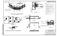
9.6 STANDARD FORMATA. Plans. Project plans as described under Section 9.4.I should be prepared using the guidance provided inthis section. Following these guides will produce plan sheets that are accurate, neat, presentable, and that willreproduce legibly.The following sections detail the format, drafting standards, and organization of the plan sheets into a PS&Eassembly.1. Format. All plan sheets should be prepared using a CADD system. There may be some exceptions, e.g.,conceptual drawing, architectural renditions, emergency projects, etc., to accommodate special needs ofinternal sections or cooperating agencies, but these should be few in number. When manual drafting becomesnecessary, it should be accomplished in a manner that duplicates the appearance of CADD drafting to theextent possible.Exhibits No. 9.22A through 9.37 were prepared using MicroStation version 5 software on an IntergraphCADD System. In addition to illustrating an acceptable format for plan sheets, the exhibits show, with the useof a hand-shaped symbol, the recommended fonts (FT), text sizes (TX), line style (LC), and weights (WT) touse in the preparation of the graphics. Lettering is shown in font 23 or 24 italics and font 1 or 2 vertical. Textsize in shown in millimeters. Line weights vary from 0 = 0.13 millimeters to 6 = 1.00 millimeters. Theexhibits were prepared using italic lettering for instructions and data relating to the construction of the project.Vertical lettering was used to indicate existing conditions. The only exception to this criteria is that streams,rivers, and lakes are always shown in vertical lettering. Backward italic lettering is used to show informationabout the development of the sheet.When other software or hardware systems are used, the line weights, line styles, text size, text style, and cellnames will vary from that shown on the exhibits. The Intergraph System with MicroStation version 5 andsubsequent versions permits many other changes the characteristics of the fonts, sizes, and weights. The planpreparer should match the exhibit plan sheets as closely as possible by following the guidance provided inTable 9-16.The plan sheets in the exhibits state whether the graphics were prepared on 864 by 558-millimeter plan sheetsor 432 by 279-millimeter plan sheets. Using the fonts, text and line criteria shown will result in uniform sizesand weights on the 432 by 279-millimeter plans sent out to potential bidders.2. Drafting Standards. The use of drafting standards establishes uniformity and quality in the drafting ofcontract plans.When a CADD system is used to develop plans, the dexterity of a manual drafter is no longer critical; letterspacing is correct and lines are uniform throughout their lengths. However, a CADD system operator musthave the same knowledge of drawing layout and detailing as a manual drafter to produce a good drawing. TheCADD operator must use care in laying out details when placing text on a plan sheet. The relationshipbetween the text and what it applies to must be clear.Notes on plan drawings should clarify the drawing and provide necessary information for a completeunderstanding of the work. Notes shall be clear, concise, descriptive, and as brief as possible to convey themessage. Plan drawings shall not include instructions covered in the specifications.CADD text shall be in the correct style and at the size specified in Table 9-16. Proper spacing between figures,symbols, and words will assure clarity, improve neatness, and increase accuracy.9 - 155


