FLH PDDM Chapter 9 - Eastern Federal Lands Highway Division
FLH PDDM Chapter 9 - Eastern Federal Lands Highway Division
FLH PDDM Chapter 9 - Eastern Federal Lands Highway Division
You also want an ePaper? Increase the reach of your titles
YUMPU automatically turns print PDFs into web optimized ePapers that Google loves.
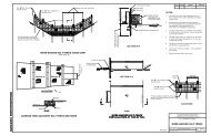
9.6. Standard Format. (continued)A completed title sheet contains the following data:Proper title and project designation.Statement of the project length.The State, county, city or town (and where applicable, the national forest, National park, etc.).Key map of the State with designator showing project location.The location or route map showing project location with beginning and ending stations or termini.Index of sheets comprising the plans.Design classifications such as the current average daily traffic (ADT), design year ADT, design hourlyvolume (DHV), directional distribution (D), percent of trucks (T), design speed (V) and maximumsuperelevation rate (e).Distance from the project to nearest city, town, etc.Provisions for dates and signatures of the approving officials.Standard specifications applicable to the project.The location or route map should be prepared using a scale ratio of 1:100 000 or larger and show the projectarea, the nearest towns appearing on a State highway map, other roads, railroads, major streams. etc. Ininstances where sufficient information cannot be placed on the route map to adequately identify the projectwork, additional vicinity maps should be prepared on separate sheets and placed following the title sheet.The large number of symbols and abbreviations used within <strong>FLH</strong> prohibits the past practice of placing theinformation on the title sheet. Therefore, the plan symbols and abbreviations sheet was developed (See Exhibit9.23) and generally follows the title sheet in a set of plans.When a special symbol is required that is not included in Exhibit 9.23, show it in a legend on either the firstplan sheet where the symbol appears or on the left side of the first plan-profile sheet. Abbreviations not shownmay be placed on the plans similar to the way symbols are placed or may be added to the contract as a specialcontract requirement under Subsection 101.03 Abbreviations.The symbols and abbreviations should not be changed on a project-to-project basis. When a change is requiredin Exhibit 9.23 to satisfy a <strong>Division</strong>'s needs, change the master file so all future projects will have the samesymbols and abbreviations. This prevents the need to check all the data on the sheet for every project.b. Typical Sections. (See Exhibit 9.25). The typical section shows the shape of the finished surface andshoulders, and represents the appearance of the completed project. It must be specific enough to describe theproposed work, its location, and the material needed.For combined roadway and bridge projects, the typical section for the bridge may be shown with other bridgedesign information. All plans should show typical sections for the project including those for bridges only andthose where abbreviated plans are used. On projects requiring more than one typical section, the limitingstations for each section should show. This may require additional plan sheets for clarification of the work.Identify all functional elements of the typical section to a relative scale. Show widths in meters and showthickness or depth in millimeters. Show the thickness of each element in the pavement structure in millimeters.Where different pavement structure thicknesses are necessary because of differing soil conditions, use notesor tables on the typical section sheet to cover such variations.9 - 159


