Oasys LS-DYNA Environment 8.1 VOLUME 3 ... - Oasys Software
Oasys LS-DYNA Environment 8.1 VOLUME 3 ... - Oasys Software
Oasys LS-DYNA Environment 8.1 VOLUME 3 ... - Oasys Software

Create successful ePaper yourself
Turn your PDF publications into a flip-book with our unique Google optimized e-Paper software.
<strong>Oasys</strong> <strong>LS</strong>-<strong>DYNA</strong> <strong>Environment</strong>: User Guide (Version <strong>8.1</strong>)<br />
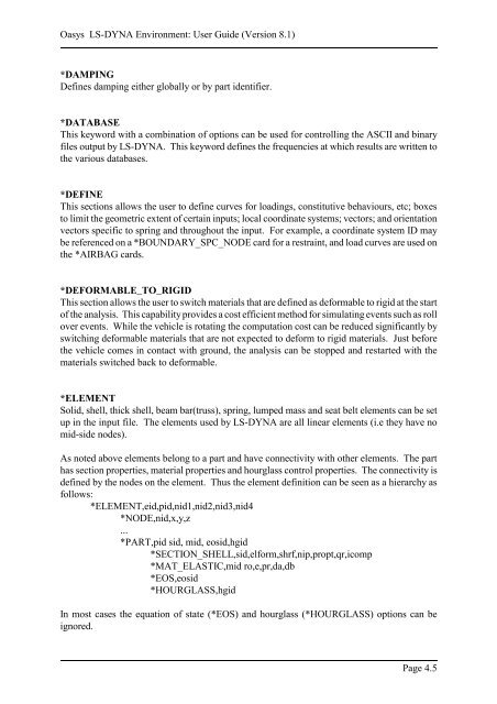
*DAMPING<br />
Defines damping either globally or by part identifier.<br />
*DATABASE<br />
This keyword with a combination of options can be used for controlling the ASCII and binary<br />
files output by <strong>LS</strong>-<strong>DYNA</strong>. This keyword defines the frequencies at which results are written to<br />
the various databases.<br />
*DEFINE<br />
This sections allows the user to define curves for loadings, constitutive behaviours, etc; boxes<br />
to limit the geometric extent of certain inputs; local coordinate systems; vectors; and orientation<br />
vectors specific to spring and throughout the input. For example, a coordinate system ID may<br />
be referenced on a *BOUNDARY_SPC_NODE card for a restraint, and load curves are used on<br />
the *AIRBAG cards.<br />
*DEFORMABLE_TO_RIGID<br />
This section allows the user to switch materials that are defined as deformable to rigid at the start<br />
of the analysis. This capability provides a cost efficient method for simulating events such as roll<br />
over events. While the vehicle is rotating the computation cost can be reduced significantly by<br />
switching deformable materials that are not expected to deform to rigid materials. Just before<br />
the vehicle comes in contact with ground, the analysis can be stopped and restarted with the<br />
materials switched back to deformable.<br />
*ELEMENT<br />
Solid, shell, thick shell, beam bar(truss), spring, lumped mass and seat belt elements can be set<br />
up in the input file. The elements used by <strong>LS</strong>-<strong>DYNA</strong> are all linear elements (i.e they have no<br />
mid-side nodes).<br />
As noted above elements belong to a part and have connectivity with other elements. The part<br />
has section properties, material properties and hourglass control properties. The connectivity is<br />
defined by the nodes on the element. Thus the element definition can be seen as a hierarchy as<br />
follows:<br />
*ELEMENT,eid,pid,nid1,nid2,nid3,nid4<br />
*NODE,nid,x,y,z<br />
...<br />
*PART,pid sid, mid, eosid,hgid<br />
*SECTION_SHELL,sid,elform,shrf,nip,propt,qr,icomp<br />
*MAT_ELASTIC,mid ro,e,pr,da,db<br />
*EOS,eosid<br />
*HOURGLASS,hgid<br />
In most cases the equation of state (*EOS) and hourglass (*HOURGLASS) options can be<br />
ignored.<br />
Page 4.5