Oasys LS-DYNA Environment 8.1 VOLUME 3 ... - Oasys Software
Oasys LS-DYNA Environment 8.1 VOLUME 3 ... - Oasys Software
Oasys LS-DYNA Environment 8.1 VOLUME 3 ... - Oasys Software

You also want an ePaper? Increase the reach of your titles
YUMPU automatically turns print PDFs into web optimized ePapers that Google loves.
<strong>Oasys</strong> <strong>LS</strong>-<strong>DYNA</strong> <strong>Environment</strong>: User Guide (Version <strong>8.1</strong>)<br />
Through-thickness directions at each node are initially normal to the element surface but rotate<br />
with the nodes. Strains are linear through the thickness. Two integration points are sufficient<br />
for linear elastic material, while more points are required for nonlinear material. Stress output<br />
gives stresses at the outermost integration points, not at the surfaces (despite the nomenclature<br />
of post-processors, which refer to top and bottom surfaces), so care is needed in interpretation<br />
of results. For elastic materials, stresses can be extrapolated to the surfaces. For nonlinear<br />
materials the usual policy is to choose four or five integration points through the thickness and<br />
to ignore the error (i.e. the difference in stress between the surface and the outermost integration<br />
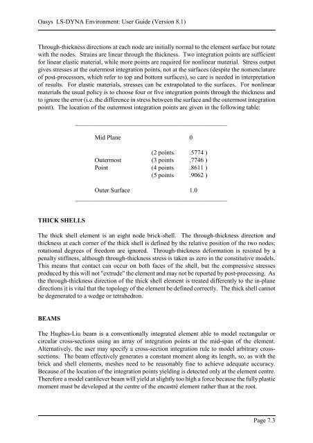
point). The location of the outermost integration points are given in the following table:<br />
THICK SHEL<strong>LS</strong><br />
________________________________________________<br />
Mid Plane 0<br />
(2 points .5774 )<br />
Outermost (3 points .7746 )<br />
Point (4 points .8611 )<br />
(5 points .9062 )<br />
Outer Surface 1.0<br />
________________________________________________<br />
The thick shell element is an eight node brick-shell. The through-thickness direction and<br />
thickness at each corner of the thick shell is defined by the relative position of the two nodes;<br />
rotational degrees of freedom are ignored. Through-thickness deformation is resisted by a<br />
penalty stiffness, although through-thickness stress is taken as zero in the constitutive models.<br />
This means that contact can occur on both faces of the shell, but the compressive stresses<br />
produced by this will not "extrude" the element and may not be reported by post-processing. As<br />
the through-thickness direction of the thick shell element is treated differently to the in-plane<br />
directions it is vital that the topology of the element be defined correctly. The thick shell cannot<br />
be degenerated to a wedge or tetrahedron.<br />
BEAMS<br />
The Hughes-Liu beam is a conventionally integrated element able to model rectangular or<br />
circular cross-sections using an array of integration points at the mid-span of the element.<br />
Alternatively, the user may specify a cross-section integration rule to model arbitrary crosssections.<br />
The beam effectively generates a constant moment along its length, so, as with the<br />
brick and shell elements, meshes need to be reasonably fine to achieve adequate accuracy.<br />
Because of the location of the integration points yielding is detected only at the element centre.<br />
Therefore a model cantilever beam will yield at slightly too high a force because the fully plastic<br />
moment must be developed at the centre of the encastré element rather than at the root.<br />
Page 7.3