- Page 3 and 4:
Control Systems
- Page 5 and 6:
III. Integrated management system12
- Page 7:
I. Individual control system1 Wirel
- Page 12 and 13:
1 Individual control system3. Wired
- Page 16 and 17:
1 Individual control system3. Wired
- Page 18 and 19:
1 Individual control system3. Wired
- Page 20 and 21:
1 Individual control system3. Wired
- Page 22 and 23:
1 Individual control system3. Wired
- Page 24 and 25:
1 Individual control system3. Wired
- Page 27 and 28:
(4) Additional functionsTracking fu
- Page 29 and 30:
Power failure of wired remote contr
- Page 31 and 32:
Service mode menu descriptionIndivi
- Page 33 and 34:
Menu Detailed description DisplayEE
- Page 35 and 36:
E.Saver - Energy saving operation m
- Page 37 and 38:
(3) Description of buttons and func
- Page 39 and 40:
CAUTION During operation mode lock,
- Page 41 and 42:
Operation checkingOperationDisplayI
- Page 43 and 44:
Connection examplesIndividual contr
- Page 45:
Group control (4)Control multiple i
- Page 48 and 49:
DVM PLUS III46
- Page 50 and 51:
2 Centralized control system1. Inte
- Page 52 and 53:
0123456789ABCDEF2 Centralized contr
- Page 54 and 55:
2 Centralized control system1. Inte
- Page 56:
2 Centralized control system2. Cent
- Page 60 and 61:
2 Centralized control system2. Cent
- Page 62 and 63:
2 Centralized control system2. Cent
- Page 64 and 65:
2 Centralized control system2. Cent
- Page 66 and 67:
2 Centralized control system3. Oper
- Page 68 and 69:
2 Centralized control system3. Oper
- Page 70 and 71:
DVM PLUS III68
- Page 72 and 73:
3 Integrated management system1. DM
- Page 74 and 75:
3 Integrated management system1. DM
- Page 76 and 77: 3 Integrated management system1. DM
- Page 78 and 79: 3 Integrated management system1. DM
- Page 80 and 81: 3 Integrated management system1. DM
- Page 82 and 83: 3 Integrated management system1. DM
- Page 84 and 85: 3 Integrated management system1. DM
- Page 86 and 87: 3 Integrated management system1. DM
- Page 88 and 89: 3 Integrated management system1. DM
- Page 90 and 91: 3 Integrated management system2. S-
- Page 92 and 93: 3 Integrated management system2. S-
- Page 94: 3 Integrated management system2. S-
- Page 97 and 98: Control• Control indoor unit/ERV
- Page 99 and 100: The 3 rd step (schedule operation s
- Page 101 and 102: Power management structure editing
- Page 103 and 104: System management Environment setti
- Page 105 and 106: DMS backup and restoration• Able
- Page 107 and 108: (3) S-NET3 log informationLogE9000E
- Page 109 and 110: 3) Main panel12345678LAN connection
- Page 111 and 112: Pattern 3Option switchDI-2DI-1Exter
- Page 113: 7) Menu(1) Main menu 1 234 5 6 7 8N
- Page 116 and 117: 3 Integrated management system3. S-
- Page 118 and 119: 3 Integrated management system3. S-
- Page 120 and 121: DVM PLUS III118
- Page 122 and 123: 4 External contact control system1.
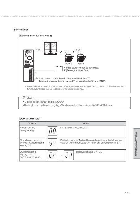
- Page 124 and 125: 4 External contact control system1.
- Page 128 and 129: 4 External contact control system2.
- Page 130 and 131: 4 External contact control system2.
- Page 132: 4 External contact control system2.
- Page 136: Control SystemsSamsung Electronics