- Page 7 and 8: PASS/FAIL ASSIGNMENT PROCEDURESIf y
- Page 9: Student CommentsCourse Title:Aviati
- Page 12 and 13: Table 1-1.-Radio-Frequency Spectrum
- Page 14 and 15: Figure 1-3.-LS-602/AI control panel
- Page 16 and 17: Figure 1-4.-Manchester encoding.thr
- Page 18 and 19: they can complete a full cycle. The
- Page 20 and 21: one-shot circuit output is directly
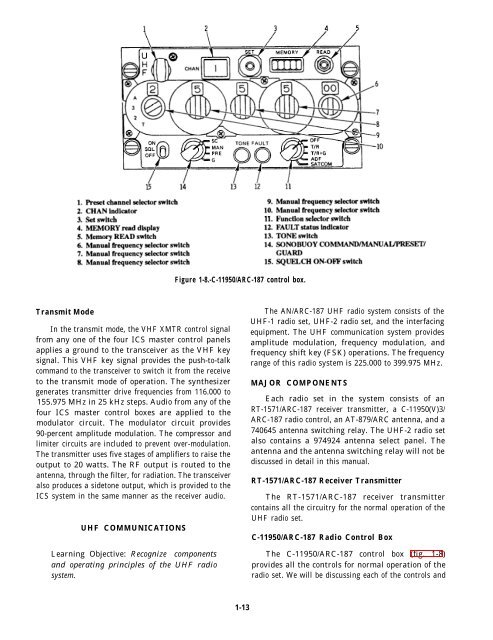
- Page 24: indicators in the following text. E
- Page 27 and 28: Figure 1-11.-C-9245/ARC-161 control
- Page 29 and 30: and the PWR/FILL switch is not in t
- Page 31 and 32: panel is in OFF. If the DTS control
- Page 33 and 34: the keyboard are sent directly. Rec
- Page 35: the signal data converter, where it
- Page 38 and 39: Navigation is both an art and a sci
- Page 40 and 41: this axis at right angles to it (fi
- Page 42 and 43: . Course is the intended horizontal
- Page 44 and 45: The standard atmosphere is theoreti
- Page 46 and 47: eadings are higher than actual. Thi
- Page 48 and 49: The barometric switch in the RAWS a
- Page 50 and 51: Major ComponentsThe AN/ARN-84(V) TA
- Page 52 and 53: the outputs is used for the automat
- Page 54 and 55: DOPPLERIn the following text we wil
- Page 57 and 58: CHAPTER 3RADARAs an avionics superv
- Page 59 and 60: the antennas will stop at the posit
- Page 61 and 62: AS-2146/APS-115 AntennaThe radar an
- Page 63 and 64: completes the processing of radar a
- Page 65 and 66: In the on-line mode, the sensor sta
- Page 67 and 68: Mode SwitchThe mode switch is pract
- Page 69 and 70: purpose of the horizon line is to i
- Page 71 and 72: Maximum range for tracking is 40,00
- Page 73 and 74:
transmit a reply when RF interrogat
- Page 75 and 76:
airspeed-altitude computer. All fra
- Page 77 and 78:
SIF reply code is identical to the
- Page 79:
In mode 4, the reply video pulse is
- Page 82 and 83:
sound wave. The frequency (in hertz
- Page 84 and 85:
to affect the rate of travel of the
- Page 86 and 87:
DOPPLER EFFECTWhen there is relativ
- Page 88 and 89:
Figure 4-7.-Transducer installed on
- Page 90 and 91:
The Sonar Detecting-Range Set AN/AQ
- Page 92 and 93:
Figure 4-16.-RO-358/ASQ-13A.mechani
- Page 94 and 95:
applies 115 volts ac to the transmi
- Page 96 and 97:
are known as angles of dip (fig. 4-
- Page 98 and 99:
feet in length and represents the f
- Page 100 and 101:
compensation is needed for the long
- Page 102 and 103:
labeled ALT COMP. This switch is us
- Page 104 and 105:
select which signal goes to which p
- Page 106 and 107:
the passive directional sonobuoy (f
- Page 108 and 109:
REVIEW QUESTIONSQ1. How was the wor
- Page 110 and 111:
TACAN signals. When localizer signa
- Page 112 and 113:
1. The HEADING NO-GO indicator illu
- Page 114 and 115:
Figure 5-7.-New optical sight with
- Page 116 and 117:
computer’s program determines whi
- Page 118 and 119:
ias circuit, horizontal and vertica
- Page 120 and 121:
Figure 5-9.-Symbology—Continued.5
- Page 122 and 123:
Figure 5-14.-Sparrow mode.Figure 5-
- Page 124 and 125:
TACTICAL DISPLAY SYSTEM INTERFACEFi
- Page 126 and 127:
electrical signal, which varies in
- Page 128 and 129:
noise-free at that level. The impor
- Page 130 and 131:
Like the random interlace, this sys
- Page 132 and 133:
The polarity of the signal develope
- Page 134 and 135:
The SEC tube has applications in ex
- Page 137 and 138:
CHAPTER 6INFRAREDThe term infrared
- Page 139 and 140:
Table 6-1.-Characteristics of IR Ra
- Page 141 and 142:
potential difference across a PN ju
- Page 143 and 144:
system increases, and the reliabili
- Page 145 and 146:
used in the Navy, their principles
- Page 147 and 148:
signals from the control servomecha
- Page 149 and 150:
Figure 6-15.-FLIR positioning/stabi
- Page 151 and 152:
Figure 6-17.-Video converter video
- Page 153 and 154:
clamping signals from the sync gene
- Page 155 and 156:
shared by both azimuth and elevatio
- Page 157 and 158:
where they are converted into three
- Page 159 and 160:
go to the azimuth/elevation heat si
- Page 161 and 162:
TARGET TRACKING SIGHT CONTROLAs men
- Page 163 and 164:
control is injected in this module.
- Page 165 and 166:
CHAPTER 7WEAPONS SYSTEMSAs a result
- Page 167 and 168:
Figure 7-5.-Master light control pa
- Page 169 and 170:
Rocket firing systemWalleye systemA
- Page 171 and 172:
The wing-form display is displayed
- Page 173 and 174:
Figure 7-15.-Emergency jettison con
- Page 175 and 176:
The A/A weapon select switch select
- Page 177 and 178:
Part of the system consists of unpr
- Page 179 and 180:
Figure 7-22.-SH-3 (series) search a
- Page 181 and 182:
ottle and the ECU are mounted on to
- Page 183 and 184:
Figure 7-25.-Pylon/rack assembly.ci
- Page 185:
REVIEW QUESTIONSQ1. True or False.
- Page 188 and 189:
COMPUTER APPLICATIONSTYPES OF COMPU
- Page 190 and 191:
the most important. This data manip
- Page 192 and 193:
and other data that are to be used
- Page 194 and 195:
to represent the same data that was
- Page 196 and 197:
compatibility permits the computer
- Page 198 and 199:
most cases, the processing speed fa
- Page 200 and 201:
4. Stores the results of manipulati
- Page 202 and 203:
An overall check of a computer can
- Page 205 and 206:
CHAPTER 9AUTOMATIC CARRIER LANDING
- Page 207 and 208:
stabilized deck-coordinated system
- Page 209 and 210:
Figure 9-3.-Mode I landing sequence
- Page 211:
Figure 9-5.-Lateral automatic wave-
- Page 214 and 215:
Precipitation StaticPrecipitation s
- Page 216 and 217:
l Sliding-contact interference. Thi
- Page 218 and 219:
the signal applied to it. These spu
- Page 220 and 221:
the following methods: short circui
- Page 222 and 223:
Figure 10-4.-Internal construction
- Page 224 and 225:
Figure 10-9.-Methods for using RC f
- Page 226 and 227:
Band-Rejection FiltersA band-reject
- Page 228 and 229:
Causes of Static ElectricityGenerat
- Page 230 and 231:
composed of carbon particles, impre
- Page 233 and 234:
APPENDIX 1REFERENCES USED TODEVELOP
- Page 235:
Chapter 7Airborne Weapons/Stores Lo
- Page 238 and 239:
CHAPTER 3A1.A2.A3.A4.A5.A6.A7.A8.A9
- Page 240 and 241:
A7. Linking two or more computers t
- Page 242 and 243:
FORMULASAIII-2
- Page 244 and 245:
AIII-4
- Page 246 and 247:
Comparison of Units in Electric and
- Page 248 and 249:
Antisubmarine warfare weapons syste
- Page 250 and 251:
Electrostatic discharge, 10-15compo
- Page 252 and 253:
Heads-up display (HUD), 5-5air-to-a
- Page 254 and 255:
NNavigation basics, 2-1airborne nav
- Page 256 and 257:
Teletype system, 1-22block diagram,
- Page 259:
Assignment QuestionsInformation: Th
- Page 262 and 263:
1-11. What will the Sillumination o
- Page 264 and 265:
1-35.1-36.1-37.1-38.UHF-1 does NOT
- Page 266 and 267:
1-59. What arethat thetactical1. Fr
- Page 268 and 269:
ASSIGNMENT 2Textbook Assignment:
- Page 270 and 271:
IN ANSWERING QUESTIONS 2-22 THROUGH
- Page 272 and 273:
2-43. What method does the AN/APN-1
- Page 274 and 275:
2-64. What distance is the maximum
- Page 276 and 277:
3-12.3-13.The antenna position prog
- Page 278 and 279:
3-32. The 128 nautical mile range i
- Page 280 and 281:
IN ANSWERING QUESTION 3-53,FIGURE 3
- Page 282 and 283:
3-74. What is the nominal peak powe
- Page 284 and 285:
4-12. Sonar transmission losses can
- Page 286 and 287:
4-31.4-32.4-33.When positive gradie
- Page 288 and 289:
4-52. The function of the dual curs
- Page 290 and 291:
4-71. The angle between a magnetic
- Page 292 and 293:
IN ANSWERING QUESTIONS 5-9 THROUGH
- Page 294 and 295:
5-29. What component contains theop
- Page 296 and 297:
5-51. What type of RF output signal
- Page 298 and 299:
ASSIGNMENT 6Textbook Assignment:
- Page 300 and 301:
6-20. On the HSI, when a tactical m
- Page 302 and 303:
6-42. What control(s) the symbolbri
- Page 304 and 305:
6-65. Which, if any, of the followi
- Page 306 and 307:
7-11. If the temperature of a black
- Page 308 and 309:
7-34.A scan mirror is indexed three
- Page 310 and 311:
7-56. What is the primary differenc
- Page 312 and 313:
ASSIGNMENT 8Textbook Assignment:
- Page 314 and 315:
8-21. With the landing gear handle
- Page 316 and 317:
8-42. With the F/A-18 AIM-9 Sidewin
- Page 318 and 319:
8-66. The jettison of wing stores I
- Page 320 and 321:
9-13. What method is used to change
- Page 322 and 323:
9-36. In magnetic core memories, a
- Page 324 and 325:
9-57. What typeaccess toof instruct
- Page 326 and 327:
10-12. To maintain the angle-of-att
- Page 328 and 329:
10-35. A receiver tuned to 2.4 kHze
- Page 330:
10-55. When rubbed against any of t