User Manual MV1-D1312(I) CameraLink®Series - Machine Vision
User Manual MV1-D1312(I) CameraLink®Series - Machine Vision
User Manual MV1-D1312(I) CameraLink®Series - Machine Vision

Create successful ePaper yourself
Turn your PDF publications into a flip-book with our unique Google optimized e-Paper software.
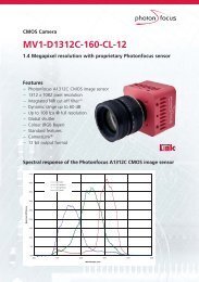
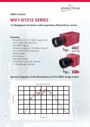
3 Product Specification60%QEResponsivity120050%100040%QuantumEfficiency30%20%800600400Responsivity [V V/J/m²]10%2000%0200 300 400 500 600 700 800 900 1000 1100Wavelength [nm]Figure 3.3: Spectral response of the A1312I image sensor (NIR) in the <strong>MV1</strong>-<strong>D1312</strong>I camera series (Hint: thered-shiftet curve corresponds to the responsivity curve.)3.4 Frame Grabber relevant ConfigurationThe parameters and settings, which are essential to configure the frame grabber are shown inthe following table. The timing diagrams of the camera are given in Section 5.3.<strong>MV1</strong>-<strong>D1312</strong>(I)-40 <strong>MV1</strong>-<strong>D1312</strong>(I)-80 <strong>MV1</strong>-<strong>D1312</strong>(I)-160Pixel Clock per Tap 40 MHz 40 MHz 80 MHzNumber of Taps 1 2 2Greyscale resolution 12 bit / 10 bit / 8 bit 12 bit / 10 bit / 8 bit 12 bit / 10 bit / 8 bitLine pause 36 clock cycles 18 clock cycles 18 clock cyclesCC1 EXSYNC EXSYNC EXSYNCCC2 not used not used not usedCC3 not used not used not usedCC4 not used not used not usedTable 3.5: Summary of parameters needed for frame grabber configurationCameraLink ® port and bit assignments are compliant with the CameraLink ® standard (see [CL]).18