User Manual MV1-D1312(I) CameraLink®Series - Machine Vision
User Manual MV1-D1312(I) CameraLink®Series - Machine Vision
User Manual MV1-D1312(I) CameraLink®Series - Machine Vision

You also want an ePaper? Increase the reach of your titles
YUMPU automatically turns print PDFs into web optimized ePapers that Google loves.
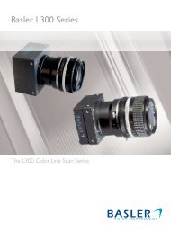
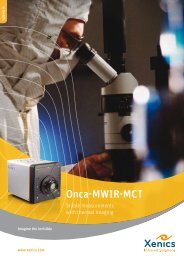
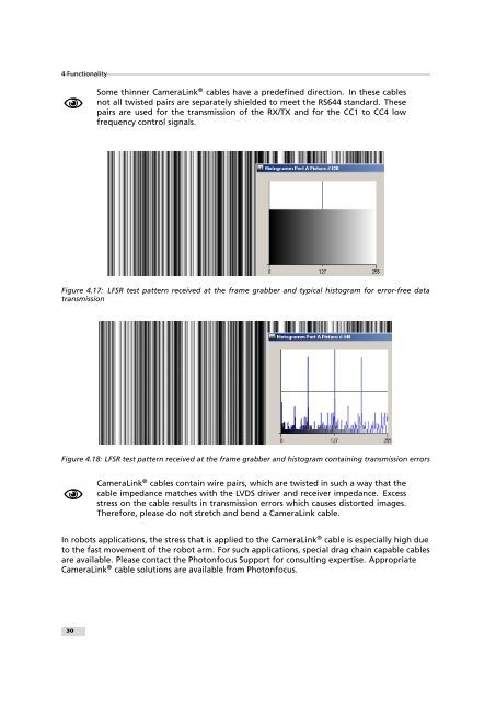
4 FunctionalitySome thinner CameraLink ® cables have a predefined direction. In these cablesnot all twisted pairs are separately shielded to meet the RS644 standard. Thesepairs are used for the transmission of the RX/TX and for the CC1 to CC4 lowfrequency control signals.Figure 4.17: LFSR test pattern received at the frame grabber and typical histogram for error-free datatransmissionFigure 4.18: LFSR test pattern received at the frame grabber and histogram containing transmission errorsCameraLink ® cables contain wire pairs, which are twisted in such a way that thecable impedance matches with the LVDS driver and receiver impedance. Excessstress on the cable results in transmission errors which causes distorted images.Therefore, please do not stretch and bend a CameraLink cable.In robots applications, the stress that is applied to the CameraLink ® cable is especially high dueto the fast movement of the robot arm. For such applications, special drag chain capable cablesare available. Please contact the Photonfocus Support for consulting expertise. AppropriateCameraLink ® cable solutions are available from Photonfocus..30