- Page 2 and 3:
Introduction to the Modeling and An
- Page 4 and 5:
iiiAbout the TextbookIntroduction t
- Page 6:
New York. He is also a Fellow of th
- Page 10 and 11:
PrefaceThis is an introductory text
- Page 12 and 13:
a comprehensive view of the related
- Page 14:
Chen, Hal Lewis, Vlad Miskovic, Chu
- Page 17 and 18:
xviCONTENTS5 Discrete-Time Models I
- Page 19 and 20:
xviiiCONTENTS15.3 Constructing Netw
- Page 22 and 23:
Chapter 1Introduction1.1 Complex Sy
- Page 24 and 25:
1.1. COMPLEX SYSTEMS IN A NUTSHELL
- Page 26 and 27:
1.2. TOPICAL CLUSTERS 7The possibil
- Page 28:
1.2. TOPICAL CLUSTERS 9these topica
- Page 31 and 32:
12 CHAPTER 2. FUNDAMENTALS OF MODEL
- Page 33 and 34:
14 CHAPTER 2. FUNDAMENTALS OF MODEL
- Page 35 and 36:
16 CHAPTER 2. FUNDAMENTALS OF MODEL
- Page 37 and 38: 18 CHAPTER 2. FUNDAMENTALS OF MODEL
- Page 39 and 40: 20 CHAPTER 2. FUNDAMENTALS OF MODEL
- Page 41 and 42: 22 CHAPTER 2. FUNDAMENTALS OF MODEL
- Page 43 and 44: 24 CHAPTER 2. FUNDAMENTALS OF MODEL
- Page 46: Part IISystems with a Small Number
- Page 49 and 50: 30 CHAPTER 3. BASICS OF DYNAMICAL S
- Page 51 and 52: 32 CHAPTER 3. BASICS OF DYNAMICAL S
- Page 53 and 54: 34 CHAPTER 3. BASICS OF DYNAMICAL S
- Page 55 and 56: 36 CHAPTER 4. DISCRETE-TIME MODELS
- Page 57 and 58: 38 CHAPTER 4. DISCRETE-TIME MODELS
- Page 59 and 60: 40 CHAPTER 4. DISCRETE-TIME MODELS
- Page 61 and 62: 42 CHAPTER 4. DISCRETE-TIME MODELS
- Page 63 and 64: 44 CHAPTER 4. DISCRETE-TIME MODELS
- Page 65 and 66: 46 CHAPTER 4. DISCRETE-TIME MODELS
- Page 67 and 68: 48 CHAPTER 4. DISCRETE-TIME MODELS
- Page 69 and 70: 50 CHAPTER 4. DISCRETE-TIME MODELS
- Page 71 and 72: 52 CHAPTER 4. DISCRETE-TIME MODELS
- Page 73 and 74: 54 CHAPTER 4. DISCRETE-TIME MODELS
- Page 75 and 76: 56 CHAPTER 4. DISCRETE-TIME MODELS
- Page 77 and 78: 58 CHAPTER 4. DISCRETE-TIME MODELS
- Page 79 and 80: 60 CHAPTER 4. DISCRETE-TIME MODELS
- Page 81 and 82: 62 CHAPTER 5. DISCRETE-TIME MODELS
- Page 83 and 84: 64 CHAPTER 5. DISCRETE-TIME MODELS
- Page 85 and 86: 66 CHAPTER 5. DISCRETE-TIME MODELS
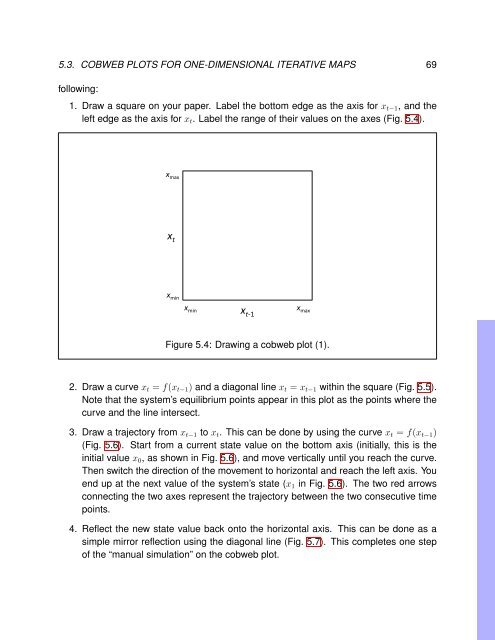
- Page 87: 68 CHAPTER 5. DISCRETE-TIME MODELS
- Page 91 and 92: 72 CHAPTER 5. DISCRETE-TIME MODELS
- Page 93 and 94: 74 CHAPTER 5. DISCRETE-TIME MODELS
- Page 95 and 96: 76 CHAPTER 5. DISCRETE-TIME MODELS
- Page 97 and 98: 78 CHAPTER 5. DISCRETE-TIME MODELS
- Page 99 and 100: 80 CHAPTER 5. DISCRETE-TIME MODELS
- Page 101 and 102: 82 CHAPTER 5. DISCRETE-TIME MODELS
- Page 103 and 104: 84 CHAPTER 5. DISCRETE-TIME MODELS
- Page 105 and 106: 86 CHAPTER 5. DISCRETE-TIME MODELS
- Page 107 and 108: 88 CHAPTER 5. DISCRETE-TIME MODELS
- Page 109 and 110: 90 CHAPTER 5. DISCRETE-TIME MODELS
- Page 111 and 112: 92 CHAPTER 5. DISCRETE-TIME MODELS
- Page 113 and 114: 94 CHAPTER 5. DISCRETE-TIME MODELS
- Page 115 and 116: 96 CHAPTER 5. DISCRETE-TIME MODELS
- Page 118 and 119: Chapter 6Continuous-Time Models I:
- Page 120 and 121: 6.2. CLASSIFICATIONS OF MODEL EQUAT
- Page 122 and 123: 6.3. CONNECTING CONTINUOUS-TIME MOD
- Page 124 and 125: 6.4. SIMULATING CONTINUOUS-TIME MOD
- Page 126 and 127: 6.4. SIMULATING CONTINUOUS-TIME MOD
- Page 128: 6.5. BUILDING YOUR OWN MODEL EQUATI
- Page 131 and 132: 112 CHAPTER 7. CONTINUOUS-TIME MODE
- Page 133 and 134: 114 CHAPTER 7. CONTINUOUS-TIME MODE
- Page 135 and 136: 116 CHAPTER 7. CONTINUOUS-TIME MODE
- Page 137 and 138: 118 CHAPTER 7. CONTINUOUS-TIME MODE
- Page 139 and 140:
120 CHAPTER 7. CONTINUOUS-TIME MODE
- Page 141 and 142:
122 CHAPTER 7. CONTINUOUS-TIME MODE
- Page 143 and 144:
124 CHAPTER 7. CONTINUOUS-TIME MODE
- Page 145 and 146:
126 CHAPTER 7. CONTINUOUS-TIME MODE
- Page 147 and 148:
128 CHAPTER 7. CONTINUOUS-TIME MODE
- Page 150 and 151:
Chapter 8Bifurcations8.1 What Are B
- Page 152 and 153:
8.2. BIFURCATIONS IN 1-D CONTINUOUS
- Page 154 and 155:
8.2. BIFURCATIONS IN 1-D CONTINUOUS
- Page 156 and 157:
8.2. BIFURCATIONS IN 1-D CONTINUOUS
- Page 158 and 159:
8.2. BIFURCATIONS IN 1-D CONTINUOUS
- Page 160 and 161:
8.3. HOPF BIFURCATIONS IN 2-D CONTI
- Page 162 and 163:
8.3. HOPF BIFURCATIONS IN 2-D CONTI
- Page 164 and 165:
8.4. BIFURCATIONS IN DISCRETE-TIME
- Page 166 and 167:
8.4. BIFURCATIONS IN DISCRETE-TIME
- Page 168 and 169:
8.4. BIFURCATIONS IN DISCRETE-TIME
- Page 170 and 171:
8.4. BIFURCATIONS IN DISCRETE-TIME
- Page 172 and 173:
Chapter 9Chaos9.1 Chaos in Discrete
- Page 174 and 175:
9.1. CHAOS IN DISCRETE-TIME MODELS
- Page 176 and 177:
Next phase space9.3. LYAPUNOV EXPON
- Page 178 and 179:
9.3. LYAPUNOV EXPONENT 159easily co
- Page 180 and 181:
9.3. LYAPUNOV EXPONENT 16110Lyapuno
- Page 182 and 183:
9.4. CHAOS IN CONTINUOUS-TIME MODEL
- Page 184 and 185:
9.4. CHAOS IN CONTINUOUS-TIME MODEL
- Page 186 and 187:
9.4. CHAOS IN CONTINUOUS-TIME MODEL
- Page 188:
9.4. CHAOS IN CONTINUOUS-TIME MODEL
- Page 192 and 193:
Chapter 10Interactive Simulation of
- Page 194 and 195:
10.2. INTERACTIVE SIMULATION WITH P
- Page 196 and 197:
10.2. INTERACTIVE SIMULATION WITH P
- Page 198 and 199:
10.2. INTERACTIVE SIMULATION WITH P
- Page 200 and 201:
10.4. SIMULATION WITHOUT PYCX 181Co
- Page 202 and 203:
10.4. SIMULATION WITHOUT PYCX 183re
- Page 204 and 205:
Chapter 11Cellular Automata I: Mode
- Page 206 and 207:
11.1. DEFINITION OF CELLULAR AUTOMA
- Page 208 and 209:
11.1. DEFINITION OF CELLULAR AUTOMA
- Page 210 and 211:
11.2. EXAMPLES OF SIMPLE BINARY CEL
- Page 212 and 213:
11.3. SIMULATING CELLULAR AUTOMATA
- Page 214 and 215:
11.3. SIMULATING CELLULAR AUTOMATA
- Page 216 and 217:
11.3. SIMULATING CELLULAR AUTOMATA
- Page 218 and 219:
11.3. SIMULATING CELLULAR AUTOMATA
- Page 220 and 221:
11.5. EXAMPLES OF BIOLOGICAL CELLUL
- Page 222 and 223:
11.5. EXAMPLES OF BIOLOGICAL CELLUL
- Page 224 and 225:
11.5. EXAMPLES OF BIOLOGICAL CELLUL
- Page 226 and 227:
11.5. EXAMPLES OF BIOLOGICAL CELLUL
- Page 228 and 229:
Chapter 12Cellular Automata II: Ana
- Page 230 and 231:
12.2. PHASE SPACE VISUALIZATION 211
- Page 232 and 233:
12.2. PHASE SPACE VISUALIZATION 213
- Page 234 and 235:
12.3. MEAN-FIELD APPROXIMATION 215E
- Page 236 and 237:
12.3. MEAN-FIELD APPROXIMATION 217T
- Page 238 and 239:
12.4. RENORMALIZATION GROUP ANALYSI
- Page 240 and 241:
12.4. RENORMALIZATION GROUP ANALYSI
- Page 242 and 243:
12.4. RENORMALIZATION GROUP ANALYSI
- Page 244:
12.4. RENORMALIZATION GROUP ANALYSI
- Page 247 and 248:
228 CHAPTER 13. CONTINUOUS FIELD MO
- Page 249 and 250:
230 CHAPTER 13. CONTINUOUS FIELD MO
- Page 251 and 252:
OutIn232 CHAPTER 13. CONTINUOUS FIE
- Page 253 and 254:
234 CHAPTER 13. CONTINUOUS FIELD MO
- Page 255 and 256:
236 CHAPTER 13. CONTINUOUS FIELD MO
- Page 257 and 258:
238 CHAPTER 13. CONTINUOUS FIELD MO
- Page 259 and 260:
240 CHAPTER 13. CONTINUOUS FIELD MO
- Page 261 and 262:
242 CHAPTER 13. CONTINUOUS FIELD MO
- Page 263 and 264:
244 CHAPTER 13. CONTINUOUS FIELD MO
- Page 265 and 266:
246 CHAPTER 13. CONTINUOUS FIELD MO
- Page 267 and 268:
248 CHAPTER 13. CONTINUOUS FIELD MO
- Page 269 and 270:
250 CHAPTER 13. CONTINUOUS FIELD MO
- Page 271 and 272:
252 CHAPTER 13. CONTINUOUS FIELD MO
- Page 273 and 274:
254 CHAPTER 13. CONTINUOUS FIELD MO
- Page 275 and 276:
256 CHAPTER 13. CONTINUOUS FIELD MO
- Page 277 and 278:
258 CHAPTER 13. CONTINUOUS FIELD MO
- Page 279 and 280:
260 CHAPTER 13. CONTINUOUS FIELD MO
- Page 281 and 282:
262 CHAPTER 13. CONTINUOUS FIELD MO
- Page 283 and 284:
264 CHAPTER 13. CONTINUOUS FIELD MO
- Page 285 and 286:
266 CHAPTER 13. CONTINUOUS FIELD MO
- Page 287 and 288:
268 CHAPTER 13. CONTINUOUS FIELD MO
- Page 289 and 290:
270 CHAPTER 14. CONTINUOUS FIELD MO
- Page 291 and 292:
272 CHAPTER 14. CONTINUOUS FIELD MO
- Page 293 and 294:
274 CHAPTER 14. CONTINUOUS FIELD MO
- Page 295 and 296:
276 CHAPTER 14. CONTINUOUS FIELD MO
- Page 297 and 298:
278 CHAPTER 14. CONTINUOUS FIELD MO
- Page 299 and 300:
280 CHAPTER 14. CONTINUOUS FIELD MO
- Page 301 and 302:
282 CHAPTER 14. CONTINUOUS FIELD MO
- Page 303 and 304:
284 CHAPTER 14. CONTINUOUS FIELD MO
- Page 305 and 306:
286 CHAPTER 14. CONTINUOUS FIELD MO
- Page 307 and 308:
288 CHAPTER 14. CONTINUOUS FIELD MO
- Page 309 and 310:
290 CHAPTER 14. CONTINUOUS FIELD MO
- Page 311 and 312:
292 CHAPTER 14. CONTINUOUS FIELD MO
- Page 313 and 314:
294 CHAPTER 14. CONTINUOUS FIELD MO
- Page 315 and 316:
296 CHAPTER 15. BASICS OF NETWORKSg
- Page 317 and 318:
298 CHAPTER 15. BASICS OF NETWORKSi
- Page 319 and 320:
300 CHAPTER 15. BASICS OF NETWORKS5
- Page 321 and 322:
302 CHAPTER 15. BASICS OF NETWORKSE
- Page 323 and 324:
304 CHAPTER 15. BASICS OF NETWORKSC
- Page 325 and 326:
306 CHAPTER 15. BASICS OF NETWORKSC
- Page 327 and 328:
308 CHAPTER 15. BASICS OF NETWORKSt
- Page 329 and 330:
310 CHAPTER 15. BASICS OF NETWORKSE
- Page 331 and 332:
312 CHAPTER 15. BASICS OF NETWORKSs
- Page 333 and 334:
314 CHAPTER 15. BASICS OF NETWORKSn
- Page 335 and 336:
316 CHAPTER 15. BASICS OF NETWORKSL
- Page 337 and 338:
318 CHAPTER 15. BASICS OF NETWORKSJ
- Page 339 and 340:
320 CHAPTER 15. BASICS OF NETWORKSF
- Page 341 and 342:
322 CHAPTER 15. BASICS OF NETWORKSr
- Page 343 and 344:
324 CHAPTER 15. BASICS OF NETWORKSE
- Page 345 and 346:
326 CHAPTER 16. DYNAMICAL NETWORKS
- Page 347 and 348:
328 CHAPTER 16. DYNAMICAL NETWORKS
- Page 349 and 350:
330 CHAPTER 16. DYNAMICAL NETWORKS
- Page 351 and 352:
332 CHAPTER 16. DYNAMICAL NETWORKS
- Page 353 and 354:
334 CHAPTER 16. DYNAMICAL NETWORKS
- Page 355 and 356:
336 CHAPTER 16. DYNAMICAL NETWORKS
- Page 357 and 358:
338 CHAPTER 16. DYNAMICAL NETWORKS
- Page 359 and 360:
340 CHAPTER 16. DYNAMICAL NETWORKS
- Page 361 and 362:
342 CHAPTER 16. DYNAMICAL NETWORKS
- Page 363 and 364:
344 CHAPTER 16. DYNAMICAL NETWORKS
- Page 365 and 366:
346 CHAPTER 16. DYNAMICAL NETWORKS
- Page 367 and 368:
348 CHAPTER 16. DYNAMICAL NETWORKS
- Page 369 and 370:
350 CHAPTER 16. DYNAMICAL NETWORKS
- Page 371 and 372:
352 CHAPTER 16. DYNAMICAL NETWORKS
- Page 373 and 374:
354 CHAPTER 16. DYNAMICAL NETWORKS
- Page 375 and 376:
356 CHAPTER 16. DYNAMICAL NETWORKS
- Page 377 and 378:
358 CHAPTER 16. DYNAMICAL NETWORKS
- Page 379 and 380:
360 CHAPTER 16. DYNAMICAL NETWORKS
- Page 381 and 382:
362 CHAPTER 16. DYNAMICAL NETWORKS
- Page 383 and 384:
364 CHAPTER 16. DYNAMICAL NETWORKS
- Page 385 and 386:
366 CHAPTER 16. DYNAMICAL NETWORKS
- Page 387 and 388:
368 CHAPTER 16. DYNAMICAL NETWORKS
- Page 390 and 391:
Chapter 17Dynamical Networks II: An
- Page 392 and 393:
17.1. NETWORK SIZE, DENSITY, AND PE
- Page 394 and 395:
17.1. NETWORK SIZE, DENSITY, AND PE
- Page 396 and 397:
17.2. SHORTEST PATH LENGTH 37717.2
- Page 398 and 399:
17.2. SHORTEST PATH LENGTH 379Eccen
- Page 400 and 401:
17.3. CENTRALITIES AND CORENESS 381
- Page 402 and 403:
17.3. CENTRALITIES AND CORENESS 383
- Page 404 and 405:
17.3. CENTRALITIES AND CORENESS 385
- Page 406 and 407:
17.4. CLUSTERING 387while the numer
- Page 408 and 409:
17.5. DEGREE DISTRIBUTION 3891.00.8
- Page 410 and 411:
17.5. DEGREE DISTRIBUTION 391er = n
- Page 412 and 413:
17.5. DEGREE DISTRIBUTION 393Pk = [
- Page 414 and 415:
17.5. DEGREE DISTRIBUTION 395logkda
- Page 416 and 417:
17.6. ASSORTATIVITY 397Assortativit
- Page 418 and 419:
17.6. ASSORTATIVITY 399>>> nx.degre
- Page 420 and 421:
17.7. COMMUNITY STRUCTURE AND MODUL
- Page 422:
17.7. COMMUNITY STRUCTURE AND MODUL
- Page 425 and 426:
406CHAPTER 18. DYNAMICAL NETWORKS I
- Page 427 and 428:
408CHAPTER 18. DYNAMICAL NETWORKS I
- Page 429 and 430:
410CHAPTER 18. DYNAMICAL NETWORKS I
- Page 431 and 432:
412CHAPTER 18. DYNAMICAL NETWORKS I
- Page 433 and 434:
414CHAPTER 18. DYNAMICAL NETWORKS I
- Page 435 and 436:
416CHAPTER 18. DYNAMICAL NETWORKS I
- Page 437 and 438:
418CHAPTER 18. DYNAMICAL NETWORKS I
- Page 439 and 440:
420CHAPTER 18. DYNAMICAL NETWORKS I
- Page 441 and 442:
422CHAPTER 18. DYNAMICAL NETWORKS I
- Page 443 and 444:
424CHAPTER 18. DYNAMICAL NETWORKS I
- Page 445 and 446:
426CHAPTER 18. DYNAMICAL NETWORKS I
- Page 447 and 448:
428 CHAPTER 19. AGENT-BASED MODELSE
- Page 449 and 450:
430 CHAPTER 19. AGENT-BASED MODELS
- Page 451 and 452:
432 CHAPTER 19. AGENT-BASED MODELST
- Page 453 and 454:
434 CHAPTER 19. AGENT-BASED MODELSI
- Page 455 and 456:
436 CHAPTER 19. AGENT-BASED MODELSt
- Page 457 and 458:
438 CHAPTER 19. AGENT-BASED MODELSF
- Page 459 and 460:
440 CHAPTER 19. AGENT-BASED MODELSY
- Page 461 and 462:
442 CHAPTER 19. AGENT-BASED MODELS3
- Page 463 and 464:
444 CHAPTER 19. AGENT-BASED MODELSn
- Page 465 and 466:
446 CHAPTER 19. AGENT-BASED MODELS0
- Page 467 and 468:
448 CHAPTER 19. AGENT-BASED MODELS1
- Page 469 and 470:
450 CHAPTER 19. AGENT-BASED MODELSF
- Page 471 and 472:
452 CHAPTER 19. AGENT-BASED MODELSe
- Page 473 and 474:
454 CHAPTER 19. AGENT-BASED MODELSf
- Page 475 and 476:
456 CHAPTER 19. AGENT-BASED MODELS1
- Page 477 and 478:
458 CHAPTER 19. AGENT-BASED MODELSi
- Page 479 and 480:
460 CHAPTER 19. AGENT-BASED MODELSw
- Page 481 and 482:
462 CHAPTER 19. AGENT-BASED MODELSi
- Page 483 and 484:
464 CHAPTER 19. AGENT-BASED MODELSB
- Page 485 and 486:
466 BIBLIOGRAPHY[12] “The Human C
- Page 487 and 488:
468 BIBLIOGRAPHY[39] H. Sayama, “
- Page 489 and 490:
470 BIBLIOGRAPHY[65] P. Holme and J
- Page 492 and 493:
Indexaction potential, 202actor, 29
- Page 494 and 495:
INDEX 475equilibrium point, 61, 111
- Page 496 and 497:
INDEX 477partial differential equat