environment
environment
environment
- No tags were found...

You also want an ePaper? Increase the reach of your titles
YUMPU automatically turns print PDFs into web optimized ePapers that Google loves.
Vol. 11 No. 1 2004<br />
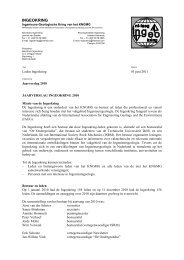
Figure 2: Fundamental difference between "funnel and gate" systems (left) and "continuous trench" systems (right).<br />
[EPA 2002].<br />
direction of flow and flow velocity of the<br />
groundwater<br />
5. suitable barrier materials and type of remediation<br />
process (chemical adsorption, physical<br />
adsorption)<br />
6. the effectivity of the physical or chemical<br />
process through implementation and interpretation<br />
of laboratory studies and numerical models<br />
Resulting design of the PRB<br />
The design process mentioned above resulted in a<br />
design with a barrier based on two materials, zeolite and<br />
iron. They are used in a “funnel and gate” type<br />
barrier for capturing fluoride and cyanide. The funnel<br />
and gate design efficiently catches the ground water<br />
flow and forces it to flow through the reactive barrier<br />
(see figure 2).<br />
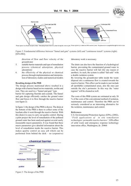
In figure 3, the design of the PRB is shown. The drain at<br />
the bottom of the PRB is there to collect some of the<br />
leachate after it went through the reactive barrier. With<br />
this drain it is easy to carry out quality control. During<br />
a pilot project the level of remediation of the polluted<br />
ground water has been analysed against several easily<br />
measurable macro parameters. It was found that these<br />
macro parameters give detailed information about the<br />
level of remediation inside the reactive barrier. This<br />
makes quality control an easy job which can be<br />
performed from behind the desk – no (expensive)<br />
laboratory work is necessary.<br />
The drain can also have the function of a hydrological<br />
barrier, preventing the contaminated ground water in<br />
case the reactive barrier will fail (for one reason or<br />
another). As such, the system is called “fail-safe” with<br />
a double isolation system.<br />
By lowering the groundwater table inside the waste<br />
disposal site a continuous flow is created towards the<br />
reactive barrier. This effect can be made to just include<br />
all (probable) contaminated areas, also the ones just<br />
outside the site’s perimeter. In this way the “outer<br />
regions” will be cleaned as well.<br />
The costs of this PRB system are estimated at only 20<br />
% of the costs of the conventional method of isolation,<br />
maintenance and control. Therefore the PRB can be<br />
seriously considered as an interesting alternative for<br />
the isolation, maintenance and control.<br />
References<br />
U.S. Environmental Protection Agency (EPA), (2002),<br />
“Field applications of in situ remediation<br />
technologies: permeable reactive barriers”, EPA office<br />
of solid waste and emergency response technology<br />
innovation office, Washington, dc 20460<br />
Figure 3: The design of the PRB<br />
15