AHG Solutions Guide_Edition 2.7
Full Product and Solutions Guide - Automatic Heating Global Pty Ltd
Full Product and Solutions Guide - Automatic Heating Global Pty Ltd

You also want an ePaper? Increase the reach of your titles
YUMPU automatically turns print PDFs into web optimized ePapers that Google loves.
Hydraulic Separators<br />
Hydraulic Separators - HVAC Accessories<br />
Contents<br />
Hydraulic Separators<br />
How does it work?<br />
The Hydraulic Separator efficiently separates the primary<br />
and secondary circuits by acting as a closely spaced tee,<br />
which is normally seen in a traditional primary-secondary<br />
piping. However it does more than just separating the<br />
circuits – this highly engineered product also acts as an air<br />
and dirt separator. The vessel is designed to create a low<br />
velocity area allowing air to rise to the top and sediment to<br />
sink to the bottom.<br />
Air Vent<br />
Flow Path #2: Flow in the secondary circuit is greater than<br />
flow in the primary circuit (refer to Figure 4). Since the<br />
flows are no longer balanced, the temperature going to the<br />
secondary circuit is no longer the same as the temperature<br />
from the boiler. This is primarily due to mixing of the supply<br />
and return fluids within the hydraulic separator body. To<br />
satisfy the system demand, a portion of the fluid returning<br />
from the system at Port 3 mixes with the fluid entering the<br />
hydraulic separator from the boiler at Port 1. This situation<br />
results in a lower temperature flow at T2 going to the system.<br />
From boiler<br />
Air rises<br />
to the<br />
top<br />
To system<br />
T 1<br />
> T 2<br />
Q 1<br />
= Q 4<br />
T 3<br />
= T 4<br />
Q 2<br />
= Q 3<br />
To boiler<br />
Insulation<br />
Sediment<br />
sinks<br />
to the<br />
bottom<br />
Drain Valve<br />
From system<br />
From boiler<br />
To boiler<br />
T T 1<br />
Q 4<br />
Q 3<br />
Q 1<br />
2<br />
Q 2<br />
Port 1 Port 2<br />
T 4<br />
T 3<br />
Port 4<br />
Port 3<br />
To system<br />
From system<br />
Figure 2: Primary-Secondary Header<br />
Figure 4<br />
HVAC ACCESSORIES<br />
There are three possible flow paths, which are all<br />
dependent on the flows within the primary and secondary<br />
circuits.<br />
Flow Path #1: Flow in the primary circuit is equal to flow in<br />
the secondary circuit (refer to Figure 3). This is an example<br />
of a balanced flow where the flow and temperature from<br />
the boiler is equal to that of the distribution system. The hot<br />
water from the boiler remains near the top two ports, Port<br />
1 and Port 2. A similar situation occurs on the bottom ports,<br />
Port 3 and Port 4 – the flow and temperature from the<br />
system are equal to the flow and temperature of the fluid<br />
going back to the boiler. In cases like this, mixing with the<br />
hydraulic separator body is very minimal.<br />
From boiler<br />
To boiler<br />
T T 1<br />
Q 4<br />
Q 3<br />
Q 1<br />
2<br />
Q 2<br />
Port 1 Port 2<br />
T 4<br />
T 3<br />
Port 4<br />
Port 3<br />
T 1<br />
= T 2<br />
Q 1<br />
= Q 4<br />
T 3<br />
= T 4<br />
Q 2<br />
= Q 3<br />
Figure 3<br />
To system<br />
From system<br />
Flow Path #3: Flow in the primary circuit is greater than<br />
flow in the secondary circuit (refer to Figure 5). This is<br />
another case of an unbalanced flow. This time, the system<br />
requirement is less than the boiler output. The flow<br />
returning from the system, Q3, mixes with the hot water<br />
from the boiler, Q1. This results in an increase in boiler<br />
return temperature. The formula to calculate T4 is shown in<br />
the appendix on the back page.<br />
From boiler<br />
To boiler<br />
T T 1<br />
Q 4<br />
Q 3<br />
Q 1<br />
2<br />
Q 2<br />
Port 1 Port 2<br />
T 4<br />
T 3<br />
Port 4<br />
Port 3<br />
T 1<br />
= T 2<br />
Q 1<br />
= Q 4<br />
T 3<br />
< T 4<br />
Q 2<br />
= Q 3<br />
Figure 5<br />
To system<br />
From system<br />
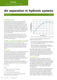
In all three cases described, the air and dirt are separated<br />
from the fluid as it enters the hydraulic separator body. The<br />
air rises to the top vessel and vented to the atmosphere<br />
via the automatic air vent while the sediment sinks to the<br />
bottom, which could be removed through the drain valve.<br />
266