CONELOG® SURGICAL PROCEDURES - Camlog
CONELOG® SURGICAL PROCEDURES - Camlog
CONELOG® SURGICAL PROCEDURES - Camlog

You also want an ePaper? Increase the reach of your titles
YUMPU automatically turns print PDFs into web optimized ePapers that Google loves.
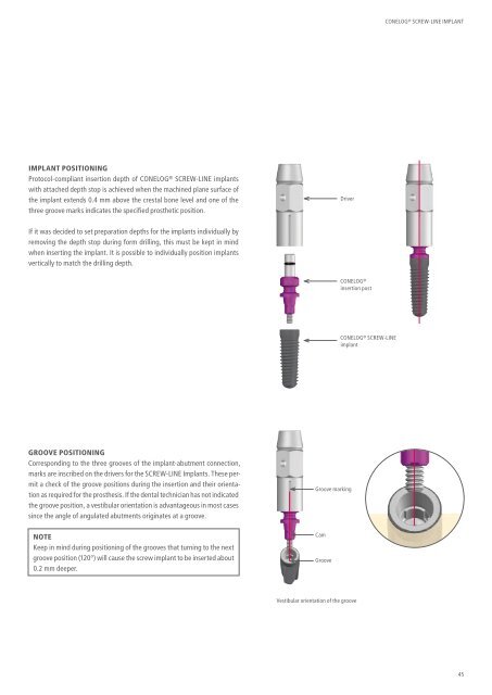
IMPLANT POSITIONING<br />
Protocol-compliant insertion depth of CONELOG ® SCREW-LINE implants<br />
with attached depth stop is achieved when the machined plane surface of<br />
the implant extends 0.4 mm above the crestal bone level and one of the<br />
three groove marks indicates the specified prosthetic position.<br />
If it was decided to set preparation depths for the implants individually by<br />
removing the depth stop during form drilling, this must be kept in mind<br />
when inserting the implant. It is possible to individually position implants<br />
vertically to match the drilling depth.<br />
GROOVE POSITIONING<br />
Corresponding to the three grooves of the implant-abutment connection,<br />
marks are inscribed on the drivers for the SCREW-LINE Implants. These permit<br />
a check of the groove positions during the insertion and their orientation<br />
as required for the prosthesis. If the dental technician has not indicated<br />
the groove position, a vestibular orientation is advantageous in most cases<br />
since the angle of angulated abutments originates at a groove.<br />
NOTE<br />
Keep in mind during positioning of the grooves that turning to the next<br />
groove position (120°) will cause the screw implant to be inserted about<br />
0.2 mm deeper.<br />
Driver<br />
Groove marking<br />
Cam<br />
Groove<br />
CONELOG ®<br />
insertion post<br />
Vestibular orientation of the groove<br />
CONELOG ® SCREW-LINE<br />
implant<br />
CONELOG ® SCREW-LINE IMPLANT<br />
45