Project Green District Energy Feasibility Study - Partners in Project ...
Project Green District Energy Feasibility Study - Partners in Project ...
Project Green District Energy Feasibility Study - Partners in Project ...

Create successful ePaper yourself
Turn your PDF publications into a flip-book with our unique Google optimized e-Paper software.
TRCA Pearson Eco-Bus<strong>in</strong>ess Zone <strong>District</strong> <strong>Energy</strong> <strong>Feasibility</strong> <strong>Study</strong> 10 April 2012<br />
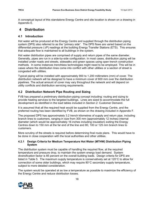
A conceptual layout of this standalone <strong>Energy</strong> Centre and site location is shown on a draw<strong>in</strong>g <strong>in</strong><br />
Appendix E.<br />
4 Distribution<br />
4.1 Introduction<br />
Hot water will be produced at the <strong>Energy</strong> Centre and supplied through the distribution pip<strong>in</strong>g<br />
system (DPS) also referred to as the “primary side”. The DPS flows are varied based on the<br />
differential pressure (∆P) read<strong>in</strong>gs at the build<strong>in</strong>g <strong>Energy</strong> Transfer Stations (ETS). This ensures<br />
that adequate flow is ma<strong>in</strong>ta<strong>in</strong>ed to all build<strong>in</strong>gs <strong>in</strong> the system.<br />
Hot water distribution pipes are comprised of supply and return pipes of the same diameter.<br />
Generally, pipes are run <strong>in</strong> a side-by-side configuration. In most cases, distribution pip<strong>in</strong>g will be<br />
<strong>in</strong>stalled under roads and streets, sidewalks and green spaces us<strong>in</strong>g open trench construction<br />
methods. In some <strong>in</strong>stances trenchless technologies might need to be employed. This will be <strong>in</strong><br />
cases where the distribution l<strong>in</strong>es come <strong>in</strong>to conflict with other utilities or a section of street is<br />
congested with utilities.<br />
Typical pip<strong>in</strong>g will be <strong>in</strong>stalled with approximately 900 to 1,200 millimeters (mm) of cover. The<br />
distribution network will be designed to have a m<strong>in</strong>imum cover of 600 mm over the distribution<br />
pipel<strong>in</strong>es. The actual amount of cover may vary throughout the network and will depend on<br />
utility conflicts and distribution servic<strong>in</strong>g requirements.<br />
4.2 Distribution Network Pipe Rout<strong>in</strong>g and Siz<strong>in</strong>g<br />
FVB has prepared a prelim<strong>in</strong>ary distribution-pip<strong>in</strong>g concept <strong>in</strong>clud<strong>in</strong>g: rout<strong>in</strong>g and siz<strong>in</strong>g to<br />
provide heat<strong>in</strong>g services to the targeted build<strong>in</strong>gs. L<strong>in</strong>es are sized to accommodate the full<br />
development as identified <strong>in</strong> the load tables <strong>in</strong>cluded <strong>in</strong> Section 2: Customer Demand.<br />
It is assumed that all the required heat would be supplied from the <strong>Energy</strong> Centre, and the<br />
preferred rout<strong>in</strong>g has been identified by FVB, as shown on the draw<strong>in</strong>g <strong>in</strong>cluded <strong>in</strong> Appendix F.<br />
The proposed DPS has approximately 3.2 trench kilometres of supply and return pipe, <strong>in</strong>clud<strong>in</strong>g<br />
branch l<strong>in</strong>es to customers, rang<strong>in</strong>g <strong>in</strong> size from 300 mm (approximately 12 <strong>in</strong>ches) <strong>in</strong>ternal<br />
diameter (which would be approximately 16 <strong>in</strong>ches <strong>in</strong>clud<strong>in</strong>g <strong>in</strong>sulation) exit<strong>in</strong>g the <strong>Energy</strong><br />
Centres down to 150 mm at the far end of the l<strong>in</strong>e and 80, 100 or 125 mm branch l<strong>in</strong>es to<br />
customers.<br />
More scrut<strong>in</strong>y of the streets is required before determ<strong>in</strong><strong>in</strong>g f<strong>in</strong>al route plans. This would have to<br />
be done <strong>in</strong> close cooperation with the local authorities and other utilities.<br />
4.2.1 Design Criteria for Medium Temperature Hot Water (MTHW) Distribution Pip<strong>in</strong>g<br />
System<br />
The distribution system must be capable of handl<strong>in</strong>g the required flow, at the required<br />
temperature and pressure drop, to ma<strong>in</strong>ta<strong>in</strong> the system energy load demand. System<br />
diversification factor is 85 percent on the overall build<strong>in</strong>g loads. Design criteria for DPS are<br />
listed <strong>in</strong> Table 5. The maximum supply temperature is conservatively set at 120°C to allow for<br />
connection of some older build<strong>in</strong>gs, which may require 80°C secondary supply temperature,<br />
subject to more detailed consideration.<br />
The system would be operated at as low a temperature as possible to maximize the efficiency of<br />
the <strong>Energy</strong> Centre and reduce distribution losses.<br />
18