Aerodynamics and Design for Ultra-Low Reynolds Number Flight
Aerodynamics and Design for Ultra-Low Reynolds Number Flight
Aerodynamics and Design for Ultra-Low Reynolds Number Flight
You also want an ePaper? Increase the reach of your titles
YUMPU automatically turns print PDFs into web optimized ePapers that Google loves.
Chapter 2<br />
Conventional airfoils have round leading edges <strong>and</strong> trailing edges that approximate a<br />
cusp. The sections considered here are typically only 2% thick with the added<br />
complexity of manufacturing constraints requiring the consideration of blunt leading <strong>and</strong><br />
trailing edges due to minimum gage constraints. As a result, a significant portion of the<br />
drag is being calculated in regions of very high surface curvature. Discretizing these<br />
airfoils creates the possibility of incurring discretization <strong>and</strong> subsequent <strong>for</strong>ce integration<br />
errors in the leading <strong>and</strong> trailing edge regions.<br />
A second issue is the possibility of excessive numerical <strong>and</strong> spatial dissipation in the<br />
solution affecting the results. INS2d has not previously been used <strong>for</strong> airfoil analysis at<br />
ultra-low <strong>Reynolds</strong> numbers <strong>and</strong> excessive dissipation could introduce errors, <strong>and</strong> in<br />
extreme cases result in solutions that erroneously appear to be steady-state.<br />
Both of these issues have been assessed, <strong>and</strong> the <strong>for</strong>ces have been verified by utilizing an<br />
off-body control-volume approach. The method applies the two-dimensional<br />
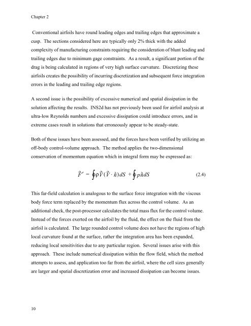
conservation of momentum equation which in integral <strong>for</strong>m may be expressed as:<br />
This far-field calculation is analogous to the surface <strong>for</strong>ce integration with the viscous<br />
body <strong>for</strong>ce term replaced by the momentum flux across the control volume. As an<br />
additional check, the post-processor calculates the total mass flux <strong>for</strong> the control volume.<br />
Instead of the <strong>for</strong>ces exerted on the airfoil by the fluid, the effect on the fluid from the<br />
airfoil is calculated. The large rounded control volume does not have the regions of high<br />
local curvature found at the surface, rather the integration area has been exp<strong>and</strong>ed,<br />
reducing local sensitivities due to any particular region. Several issues arise with this<br />
approach. These include numerical dissipation within the flow field, which the method<br />
attempts to assess, <strong>and</strong> application too far from the airfoil, where the cell sizes generally<br />
are larger <strong>and</strong> spatial discretization error <strong>and</strong> increased dissipation can become issues.<br />
10<br />
∫°<br />
F′ =<br />
ρV( V ⋅ n)<br />
dS<br />
+ ∫° pndS (2.4)


