

Aerodynamics and Design for Ultra-Low Reynolds Number Flight
Aerodynamics and Design for Ultra-Low Reynolds Number Flight
Aerodynamics and Design for Ultra-Low Reynolds Number Flight

You also want an ePaper? Increase the reach of your titles
YUMPU automatically turns print PDFs into web optimized ePapers that Google loves.
Chapter 3<br />
34<br />
Cl<br />
0.60<br />
0.50<br />
0.40<br />
0.30<br />
0.20<br />
0.10<br />
0.00<br />
-0.10<br />
-0.20<br />
-2 -1 0 1 2 3<br />
α (deg.)<br />
4 5 6 7 8<br />
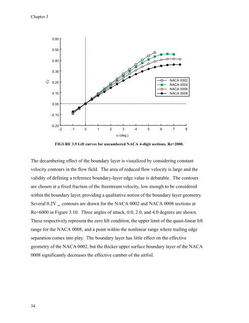
FIGURE 3.9 Lift curves <strong>for</strong> uncambered NACA 4-digit sections, Re=2000.<br />
The decambering effect of the boundary layer is visualized by considering constant<br />
velocity contours in the flow field. The area of reduced flow velocity is large <strong>and</strong> the<br />
validity of defining a reference boundary-layer edge value is debatable. The contours<br />
are chosen at a fixed fraction of the freestream velocity, low enough to be considered<br />
within the boundary layer, providing a qualitative notion of the boundary layer geometry.<br />
Several 0.2V contours are drawn <strong>for</strong> the NACA 0002 <strong>and</strong> NACA 0008 sections at<br />
Re=6000 in Figure 3.10. Three angles of attack, 0.0, 2.0, <strong>and</strong> 4.0 degrees are shown.<br />
These respectively represent the zero lift condition, the upper limit of the quasi-linear lift<br />
range <strong>for</strong> the NACA 0008, <strong>and</strong> a point within the nonlinear range where trailing edge<br />
separation comes into play. The boundary layer has little effect on the effective<br />
geometry of the NACA 0002, but the thicker upper surface boundary layer of the NACA<br />
0008 significantly decreases the effective camber of the airfoil.<br />
NACA 0002<br />
NACA 0004<br />
NACA 0006<br />
NACA 0008

