

Aerodynamics and Design for Ultra-Low Reynolds Number Flight
Aerodynamics and Design for Ultra-Low Reynolds Number Flight
Aerodynamics and Design for Ultra-Low Reynolds Number Flight

Create successful ePaper yourself
Turn your PDF publications into a flip-book with our unique Google optimized e-Paper software.
Chapter 3<br />
Further analyses have investigated the possible benefits of varying the magnitude <strong>and</strong><br />
distribution of camber. The design space has been explored using nine airfoils spanning<br />
2% to 6% maximum camber located at 30%, 50%, <strong>and</strong> 70% chord. All of the sections<br />
are 2% thick NACA 4-digit profiles. All calculations have been completed at<br />
Re=12,000.<br />
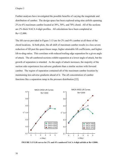
The lift curves provided in Figure 3.13 are <strong>for</strong> 2% <strong>and</strong> 4% camber at all three of the<br />
chord locations. In both plots, the aft shift of maximum camber results in a less severe<br />
reduction of lift past the quasi-linear range, higher attainable lift coefficients, <strong>and</strong> higher<br />
lift-to-drag ratios. This correlates with reduced trailing edge separation <strong>for</strong> a given angle<br />
of attack. The aft cambered sections exhibit separation at a lower angle of attack, but the<br />
growth of separation is retarded. As the angle of attack increases, the majority of the<br />
suction side experiences less adverse gradients than a similar section with <strong>for</strong>ward<br />
camber. The region of separation contained aft of the maximum camber location by<br />
maintaining less adverse gradients ahead of it. The aft concentration of camber<br />
functions like a separation ramp in the pressure distribution [22].<br />
38<br />
C l<br />
0.7<br />
0.6<br />
0.5<br />
0.4<br />
0.3<br />
0.2<br />
0.1<br />
NACA 2X02 Lift Curves<br />
Re=12000<br />
NACA 2302<br />
NACA 2502<br />
NACA 2702<br />
0 1 2 3 4 5<br />
α (deg.)<br />
0 1 2 3 4 5<br />
α (deg.)<br />
FIGURE 3.13 Lift curves <strong>for</strong> 2% <strong>and</strong> 4% cambered NACA 4-digit airfoils at Re=12000.<br />
C l<br />
0.7<br />
0.6<br />
0.5<br />
0.4<br />
0.3<br />
0.2<br />
0.1<br />
NACA 4X02 Lift Curves<br />
Re=12000<br />
NACA 4302<br />
NACA 4502<br />
NACA 4702

