REMS SSM 160 R REMS SSM 160 K REMS SSM 250 K REMS SSM ...
REMS SSM 160 R REMS SSM 160 K REMS SSM 250 K REMS SSM ...
REMS SSM 160 R REMS SSM 160 K REMS SSM 250 K REMS SSM ...

You also want an ePaper? Increase the reach of your titles
YUMPU automatically turns print PDFs into web optimized ePapers that Google loves.
eng eng<br />
1.2. Capacity <strong>SSM</strong> <strong>160</strong> R <strong>SSM</strong> <strong>160</strong> K <strong>SSM</strong> <strong>250</strong> K <strong>SSM</strong> 315 RF<br />
Pipe diameter 40 – <strong>160</strong> mm 40 – <strong>160</strong> mm 75 – <strong>250</strong> mm 90 – 315 mm<br />
All weldable plastics<br />
for sanitary installation, drain pipes, chimney reconstruction,with welding temperatures 180 – 290°C.<br />
1.3. Electric data<br />
Rated voltage (mains,voltage) 230 V 230 V 230 V 230 V<br />
Rated power input 1700 W 1700 W 1800 W 2800 W<br />
Butt welding unit 1200 W 1200 W 1300 W 2300 W<br />
Electric facing cutter 500 W 500 W 500 W 500 W<br />
Rated frequency 50 – 60 Hz 50 – 60 Hz 50 – 60 Hz 50 – 60 Hz<br />
Protection class all units protection class 1 (earth conductor)<br />
1.4. Dimensions<br />
Transport L 665 mm 835 mm 800 mm 1230 mm<br />
W 520 mm 565 mm 520 mm 680 mm<br />
H 820 mm 760 mm 760 mm 1030 mm<br />
Operation L 665 mm 1055 mm 1350 mm 1230 mm<br />
W 610 mm 925 mm 800 mm 1220 mm<br />
H 1210 mm 1310 mm 1450 mm 1500 mm<br />
1.5. Weight<br />
Machine 47.7 kg 98.5 kg 100 kg 158 kg<br />
Clamp, support inserts 17.2 kg 13.85 kg 15 kg 64 kg<br />
1.6. Noise information<br />
Emission at workplace 85 dB (A) 85 dB (A) 85 dB (A) 85 dB (A)<br />
1.7. Vibrations<br />
Weighted effective value of acceleration 2.5 m/s² 2.5 m/s² 2.5 m/s² 2.5 m/s²<br />
The indicated weighted effective value of acceleration has been measured against standard test procedures and can be used by way of comparison with another<br />
device. The indicated weighted effective value of acceleration can also be used as a preliminary evaluation of the exposure.<br />
Attention: The indicated weighted effective value of acceleration can differ during operation from the indicated value, dependent on the manner in which the device<br />
is used. Dependent upon the actual conditions of use (periodic duty) it may be necessary to establish safety precautions for the protection of the operator.<br />
2. Preparations for use<br />
2.1. Transporting and setting up the machine<br />
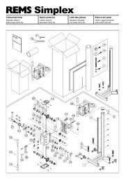
<strong>REMS</strong> <strong>SSM</strong> <strong>160</strong> R<br />
The machine is delivered and transported or set up as shown in Fig. 2. The<br />
clamping and pipe support inserts and operating key are transported or kept<br />
in a separate steel case (1). The steel case can be hung up under the machine<br />
on the stand. The machine is attached to the stand with 4 clamping claws (4).<br />
In transport the protection cover (40) must unhinged from the heating element.<br />
The machine can also be attached to a workbench.<br />
<strong>REMS</strong> <strong>SSM</strong> <strong>160</strong> K and <strong>REMS</strong> <strong>SSM</strong> <strong>250</strong> K<br />
The machine is delivered and transported or set up as shown in Fig. 3. The<br />
clamping and pipe support inserts and operating key are transported or stored<br />
in a separate drawer (8) in the steel base. To set up the machine, release the<br />
four catches (9) at the bottom of the transport case. Lift up the case and place<br />
it on the floor so that the four catches are next to the floor. Now place the<br />
machine on the carrying case.<br />
CAUTION Take care to ensure that the drawer (8) does not fall out.<br />
The machine is centred in the rectangular recess in the top of the case. For<br />
transporting purposes, proceed in the reverse order. The machine can be<br />
secured to a workbench if required.<br />
A plastic cover is available to protect the heating element in transit. This must<br />
be removed without fail before the heating element is switched on or, for transporting<br />
purposes, only after the heating element has cooled, otherwise the<br />
cover will be destroyed and the machine damaged.<br />
<strong>REMS</strong> <strong>SSM</strong> 315 RF<br />
The machine is delivered and transported or set up as shown in Fig. 4. The<br />
clamping and pipe support inserts and operating key are transported and kept<br />
in a separate box (1) .To set up the machine, release the tow bar (10) from the<br />
bayonet catch (11) and remove. Rotate the machine about the transverse axis<br />
(tubular stand axis) so that the wheel assembly is facing upwards. Release<br />
locking lever (12).<br />
CAUTION In doing so, hold the machine securely onto the frame.<br />
Swivel the machine carefully about the longitudinal axis, resecure locking lever<br />
(12). For transporting purposes, proceed in the reverse order. The machine<br />
can be used on the transit chassis if the tubular stand is removed by removing<br />
the two opposing allen screws (3) and releasing the locking lever (12). To mount<br />
the machine on a workbench, the support (14) and wheeled frame (15) must<br />
be removed in addition to the tubular stand.<br />
2.2. Electrical connection<br />
Before connecting the machine to the power supply, check that the voltage<br />
specified on the rating plate complies with the mains voltage. The welder (5)<br />
is supplied complete with its own connecting lead, so it also essential to check<br />
the voltage on the rating plate for conformity with the mains.<br />
2.3. Positioning the welder and facing cutter<br />
The welding unit can be removed from every model in this series and used as<br />
a hand-operated machine. In the case of the <strong>REMS</strong> <strong>SSM</strong> <strong>160</strong> R and <strong>REMS</strong><br />
<strong>SSM</strong> <strong>160</strong> K, it is installed the mounting (17) by the hand-grip (16), while in the<br />
case of the <strong>REMS</strong> <strong>SSM</strong> <strong>250</strong> K and <strong>REMS</strong> <strong>SSM</strong> 315 RF, it is secured with an<br />
additional plug.<br />
CAUTION When the appliance is hot, grasp it only by the hand-grip<br />
(16). Never touch the heating element or metal components between the<br />
hand-grip and heating element, otherwise a burn injury may result.<br />
<strong>REMS</strong> <strong>SSM</strong> <strong>160</strong>R:<br />
The heating element – butt welding unit (5) should not be centred after transporting<br />
the machine, as this is already set when delivered.<br />
<strong>REMS</strong> <strong>SSM</strong> <strong>160</strong> K, <strong>250</strong> K and <strong>REMS</strong> <strong>SSM</strong> 315 RF<br />
After the machine has been transported, the welder (5) must be centred. For<br />
this purpose, release clamping lever (22) and pull back the retainer (17) of the<br />
welder (5) on the sliding block (21) as far as it will go. Now re-tighten the<br />
clamping lever (22).<br />
Swivel out the welder (5) and facing cutter (6). Before moving the welder (5)<br />
and facing cutter (6) sideways, slightly raise the handle (18) or (20), otherwise<br />
the end-stop will apply a braking effect.<br />
2.4. Electronic temperature control<br />
According to DIN 15960 and DVS 2208, Part 1, the temperature of the heat ing<br />
element should be capable of being adjusted in fine stages. In order to ensure<br />
that the heating element operates at the required constant temperature, these<br />
machines are equipped with a thermostat. DVS standard 2208, Part 1 specifies<br />
a maximum differential of 3°C between the preset and actual temperatures. In<br />
practice, this degree of accuracy cannot be achieved mechanically, but only<br />
by an electronic thermostat. For this reason, therefore, welding machines<br />
operating at a fixed, preset temperature or employing a mechanical thermostat<br />
may not be used for welding operations as described in DVS 2207.<br />
The temperature can be adjusted on all <strong>REMS</strong> welders. All models are supplied<br />
with electronic thermostats. The butt welding unit is identified on the welder<br />
rating plate by code letters, example of which is given below.<br />
<strong>REMS</strong> SSG 180 EE: Adjustable temperature (E), electronic thermostat (E).<br />
The preset temperature is adjusted to within ± 1°C, i.e. with a preset temperature<br />
of 210°C (welding temperature for PE) the actual temperature will fluctuate<br />
between 209°C and 211°C.<br />
2.5. Preheating the butt welding unit<br />
The welder connecting lead is plugged into the socket (23) at the rear of the<br />
facing cutter housing. As soon as this lead is connected to the mains, the<br />
machine is ready to operate and the heating element will begin to heat up. The<br />
red power-on indicator lamp (24) and green temperature indicator lamp (25)<br />
light up. The machine requires about 10 minutes to heat up. Once the required<br />
preset temperature is reached, the built-in thermostat cuts out the power supply<br />
to the heating element. The red indicator lamp continues to glow. The green<br />
temperature indicator lamp of the electronic thermostat (EE) will light up intermittently,<br />
indicating the repeated switching on and off of the power supply. After<br />
a further 10 minutes waiting time (DVS 2207, Part 1), welding operations can<br />
begin.