F224d Faria, Rubens Alexandre de Desenvolvimento de ... - UTFPR
F224d Faria, Rubens Alexandre de Desenvolvimento de ... - UTFPR
F224d Faria, Rubens Alexandre de Desenvolvimento de ... - UTFPR

You also want an ePaper? Increase the reach of your titles
YUMPU automatically turns print PDFs into web optimized ePapers that Google loves.
AT89C52<br />
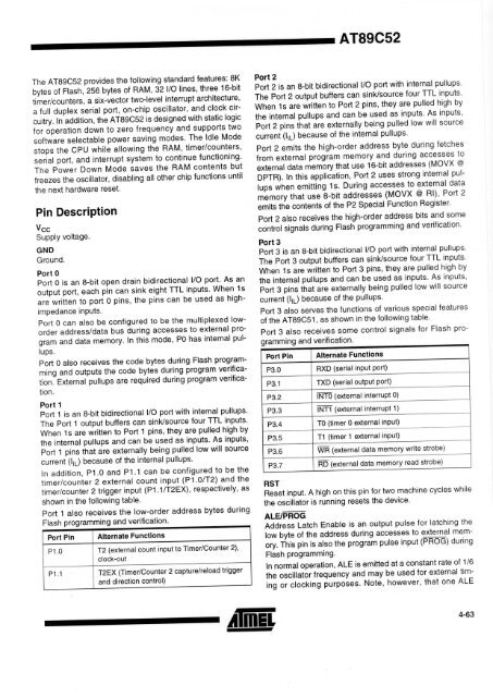
The AT89C52 provi<strong>de</strong>s the following standard features: 8K<br />
bytes of Flash, 256 bytes of RAM, 32 I/O lines, three 16-bit<br />
timer/counters, a six-vector two-level interrupt architecture,<br />
a full duplex serial port, on-chip oscillator, and clock circuitry.<br />
In addition, the AT89C52 is <strong>de</strong>signed with static logic<br />
for operation down to zero frequency and supports two<br />
software selectable power saving mo<strong>de</strong>s. The Idle Mo<strong>de</strong><br />
stops the CPU while allowing the RAM, timer/counters,<br />
serial port, and interrupt system to continue functioning.<br />
The Power Down Mo<strong>de</strong> saves the RAM contents but<br />
freezes the oscillator, disabling all other chip functions until<br />
the next hardware reset.<br />
Pin Description<br />
Vcc<br />
Supply voltage.<br />
GND<br />
Ground.<br />
Port 0<br />
Port 0 is an 8-bit open drain bidirectional I/O port. As an<br />
output port, each pin can sink eight TTL inputs. When 1s<br />
are written to port 0 pins, the pins can be used as highimpedance<br />
inputs.<br />
Port 0 can also be configured to be the multiplexed lowor<strong>de</strong>r<br />
address/data bus during accesses to external program<br />
and data memory. In this mo<strong>de</strong>, PO has internal pullups.<br />
Port 0 also receives the co<strong>de</strong> bytes during Flash programming<br />
and outputs the co<strong>de</strong> bytes during program verification.<br />
External pullups are required during program verification.<br />
Port 1<br />
Port 1 is an 8-bit bidirectional I/O port with internal pullups.<br />
The Port 1 output buffers can sink/source four TTL inputs.<br />
When 1s are written to Port 1 pins, they are pulled high by<br />
the internal pullups and can be used as inputs. As inputs,<br />
Port 1 pins that are externally being pulled low will source<br />
current (I L) because of the internal pullups.<br />
In addition, P1.0 and P1.1 can be configured to be the<br />
timer/counter 2 external count input (P1.0/T2) and the<br />
timer/counter 2 trigger input (P1.1/T2EX), respectively, as<br />
shown in the following table.<br />
Port 1 also receives the low-or<strong>de</strong>r address bytes during<br />
ro rammin _ and verification.<br />
Port Pin<br />
Alternate Functions<br />
P1.0 T2 (external count input to Timer/Counter 2),<br />
clock-out<br />
P1.1 T2EX (Timer/Counter 2 capture/reload trigger<br />
and direction control)<br />
Port 2<br />
Port 2 is an 8-bit bidirectional I/O port with internal pullups.<br />
The Port 2 output buffers can sink/source four TTL inputs.<br />
When 1s are written to Port 2 pins, they are pulled high by<br />
the internal pullups and can be used as inputs. As inputs,<br />
Port 2 pins that are externally being pulled low will source<br />
current (I L) because of the internal pullups.<br />
Port 2 emits the high-or<strong>de</strong>r address byte during fetches<br />
from external program memory and during accesses to<br />
external data memory that use 16-bit addresses (MOVX @<br />
DPTR). In this application, Port 2 uses strong internal pullups<br />
when emitting 1s. During accesses to external data<br />
memory that use 8-bit addresses (MOVX @ RI), Port 2<br />
emits the contents of the P2 Special Function Register.<br />
Port 2 also receives the high-or<strong>de</strong>r address bits and some<br />
control signals during Flash programming and verification.<br />
Port 3<br />
Port 3 is an 8-bit bidirectional I/O port with internal pullups.<br />
The Port 3 output buffers can sink/source four TTL inputs.<br />
When 1s are written to Port 3 pins, they are pulled high by<br />
the internal pullups and can be used as inputs. As inputs,<br />
Port 3 pins that are externally being pulled low will source<br />
current (l ip) because of the pullups.<br />
Port 3 also serves the functions of various special features<br />
of the AT89C51, as shown in the following table.<br />
Port 3 also receives some control signals for Flash promin<br />
.., and verification.<br />
.<br />
Port Pin<br />
Alternate Functions<br />
P3.0 RXD (serial input port)<br />
P3.1 TXD (serial output port)<br />
P3.2 INTO (external interrupt 0)<br />
P3.3 INT1 (external interrupt 1)<br />
P3.4 TO (timer 0 external input)<br />
P3.5 T1 (timer 1 external input)<br />
P3.6 WR (external data memory write strobe)<br />
P3.7 RD (external data memory read strobe)<br />
RST<br />
Reset input. A high on this pin for two machine cycles while<br />
the oscillator is running resets the <strong>de</strong>vice.<br />
ALE/PROG<br />
Address Latch Enable is an output pulse for latching the<br />
low byte of the address during accesses to external memory.<br />
This pin is also the program pulse input (PROG) during<br />
Flash programming.<br />
In normal operation, ALE is emitted at a constant rate of 1/6<br />
the oscillator frequency and may be used for external timing<br />
or clocking purposes. Note, however, that one ALE<br />
4-63