Anhang i. Simulationsmodell - FG Mikroelektronik, TU Berlin
Anhang i. Simulationsmodell - FG Mikroelektronik, TU Berlin
Anhang i. Simulationsmodell - FG Mikroelektronik, TU Berlin

Sie wollen auch ein ePaper? Erhöhen Sie die Reichweite Ihrer Titel.
YUMPU macht aus Druck-PDFs automatisch weboptimierte ePaper, die Google liebt.
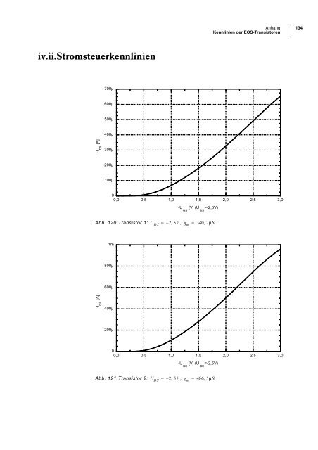
iv.ii.Stromsteuerkennlinien<br />
-I DS [A]<br />
-I DS [A]<br />
700µ<br />
600µ<br />
500µ<br />
400µ<br />
300µ<br />
200µ<br />
100µ<br />
Abb. 120:Transistor 1: = – 25V , , gm = 340, 7μS<br />
800µ<br />
600µ<br />
400µ<br />
200µ<br />
Abb. 121:Transistor 2: = – 25V , , gm =<br />
486, 5μS<br />
<strong>Anhang</strong> 134<br />
Kennlinien der EOS-Transistoren<br />
0<br />
0,0 0,5 1,0 1,5 2,0 2,5 3,0<br />
1m<br />
U DS<br />
-U GS [V] (U DS =-2,5V)<br />
0<br />
0,0 0,5 1,0 1,5 2,0 2,5 3,0<br />
U DS<br />
-U GS [V] (U DS =-2,5V)