Observations and Modelling of Fronts and Frontogenesis
Observations and Modelling of Fronts and Frontogenesis
Observations and Modelling of Fronts and Frontogenesis
Create successful ePaper yourself
Turn your PDF publications into a flip-book with our unique Google optimized e-Paper software.
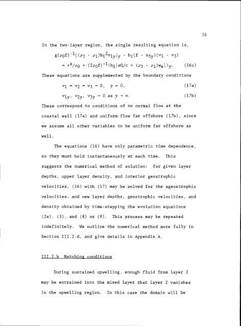
In the two-layer region, the single resulting equation is,<br />
g(pf)[(p3 Pl)hl2vly]y h1(f u3y)(vl - v3)<br />
+ (2p0f)(h1[aQ/c + (P3 Pl)we])y. (16c)<br />
These equations are supplemented by the boundary conditions<br />
v1.v2v3O, y=O, (l7a)<br />
vly v2y V3y 0 as y .<br />
(l7b)<br />
These correspond to conditions <strong>of</strong> no normal flow at the<br />
coastal wall (l7a) <strong>and</strong> uniform flow far <strong>of</strong>fshore (17b), since<br />
we assume all other variables to be uniform far <strong>of</strong>fshore as<br />
well.<br />
The equations (16) have only parametric time dependence,<br />
so they must hold instantaneously at each time. This<br />
suggests the numerical method <strong>of</strong> solution: for given layer<br />
depths, upper layer density, <strong>and</strong> interior geostrophic<br />
velocities, (16) with (17) may be solved for the ageostrophic<br />
velocities, <strong>and</strong> new layer depths, geostrophic velocities, <strong>and</strong><br />
density obtained by time-stepping the evolution equations<br />
(2a), (3), <strong>and</strong> (8) or (9). This process may be repeated<br />
indefinitely. We outline the numerical method more fully in<br />
Section III.2.d, <strong>and</strong> give details in Appendix A.<br />
III.2.b Matching conditions<br />
During sustained upwelling, enough fluid from layer 2<br />
may be entrained into the mixed layer that layer 2 vanishes<br />
in the upwelling region. In this case the domain will be<br />
56


