- Page 1:
TOSHIBASYSTEM PRACTICES OIGITALKEYT
- Page 5:
PARAGRAPH 1 2 3 3.10 3.20 3.30 3.40
- Page 8 and 9:
INSTALLATION-INTRODUCTION SECTION 1
- Page 10 and 11:
INSTALLATION-INTRODUCTION SECTION 1
- Page 13:
TOSHIBASYSTEM PRACTICES OIGITALKEYT
- Page 17 and 18:
1 GENERAL 1 .OO This chapter define
- Page 19 and 20:
GENERAL Primary power Input AC AC f
- Page 21:
TOSHIBA SYSTEM PRACTICES DIGITAL KE
- Page 24 and 25:
INSTALLATION-CONFIGURATION SECTION
- Page 26 and 27:
INSTALLATION-CONFIGURATION SECTION
- Page 28 and 29:
INSTALLATION-CONFIGURATION SECTION
- Page 30 and 31:
INSTALLATION-CONFIGURATION SECTION
- Page 32 and 33:
INSTALLATION-CONFIGURATION SECTION
- Page 34 and 35:
INSTALLATION-CONFIGURATION SECTION
- Page 36 and 37:
INSTALLATION-CONFIGURATION SECTION
- Page 38 and 39:
INSTALLATION-CONFIGURATION SECTION
- Page 40 and 41:
INSTALLATION-CONFIGURATION SECTION
- Page 43:
TOSHIBASYSTEM PRACTICES OIGITALKEYT
- Page 46 and 47:
INSTALLATION-DK8KSU & PCB SECTION l
- Page 48 and 49:
INSTALLATION-OK8KSU&PCB SECTION lOO
- Page 50 and 51:
INSTALLATION-OK8 KSU & PC8 SECTION
- Page 52 and 53:
INSTALLATION-OK8KSU 81 PCB SECTION
- Page 54 and 55:
INSTALLATION-DK8KSU &PCB SECTION lO
- Page 56 and 57:
INSTALLATION-DK8KSU & PCB SECTION l
- Page 58 and 59:
INSTALLATION-OK8 KSU & PCB SECTION
- Page 60 and 61:
INSTALLATIONGK8 KSU 81 PCB SECTION
- Page 62 and 63:
INSTALLATION-DK8 KSU 81 PCB SECTION
- Page 65:
TOSHIBASYSTEM PRACTICES OIGITALKEYT
- Page 68 and 69:
. . INSTALLATION-DKlGKSU&PCB SECTIO
- Page 70 and 71:
INSTALLATION-OKIGKSU &PCB SECTION l
- Page 72 and 73:
INSTALLATION-OK16KSU & PCB SECTION
- Page 74 and 75:
INSTALLATION-OK16 KSU & PCB SECTION
- Page 76 and 77: INSTALLATION-OK16 KSU &PCB SECTION
- Page 78 and 79: INSTALLATION-DKlGKSU & PCB SECTION
- Page 80 and 81: INSTALLATION-OK16 KSU & PCB SECTION
- Page 82 and 83: INSTALLATION-DK16 KSU & PCB SECTION
- Page 84 and 85: INSTALLATION-DK 16 KSU & PCB SECTIO
- Page 86 and 87: INSTALLATION-OK 16 KSU 81 PCB SECTI
- Page 88 and 89: INSTALLATION-DK 16 KSU & PCB SECTIO
- Page 90 and 91: INSTALLATION-DK 16 KSU & PCB SECTIO
- Page 92 and 93: INSTALLATION-OK 16 KSU & PCB SECTIO
- Page 94 and 95: INSTALLATION-DK 16 KSU & PCB SECTIO
- Page 96 and 97: INSTALLATION-DK 16 KSU & PCB SECTIO
- Page 98 and 99: INSTALLATION-OK 16 KSU & PCB SECTIO
- Page 100 and 101: INSTALLATION-DK 16 KSU & PCB SECTIO
- Page 102 and 103: INSTALLATION-DK 16 KSU 81 PCB SECTI
- Page 104 and 105: INSTALLATION-DK 16 KSU & PCB SECTIO
- Page 106 and 107: INSTALLATION-DK 16 KSU & PCB SECTIO
- Page 109 and 110: TABLEOFCONTENTS INSTALLATION-STATIO
- Page 111 and 112: 1 .OO Purpose 1 OVERVIEW 1 .Ol This
- Page 113 and 114: HANDSET HANGER FIGURE 6-1 REMOVING
- Page 115 and 116: FIGURE 6-4 PDIU-DIP INSTALLATION IN
- Page 117 and 118: FIGURE 6-7 DKTPOlO-HSTRAPANDCDNNECT
- Page 119 and 120: Bell-even if a headset is also inst
- Page 121 and 122: 1) Loosen the four captive screws s
- Page 123 and 124: the base (Figure 6-l). The HHEU mod
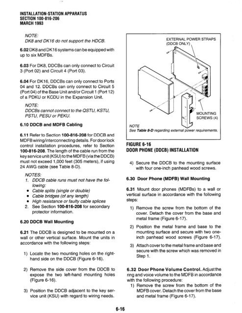
- Page 125: NOTE: 1. DDSS console cable runs mu
- Page 129: TOSHIBA SYSTEM PRACTICES DIGITAL KE
- Page 132 and 133: INSTALLATION-PERIPHERALS SECTION lO
- Page 134 and 135: INSTALLATION-PERIPHERALS SECTiON lO
- Page 136 and 137: INSTALLATION-PERIPHERALS SECTION 10
- Page 138 and 139: INSTALLATION-PERIPHERALS SECTION lO
- Page 140 and 141: INSTALLATION-PERIPHERALS SECTION 10
- Page 142 and 143: INSTALLATION-PERIPHERALS SECTION lO
- Page 144 and 145: INSTALLATION-PERIPHERALS SECTION 10
- Page 146 and 147: INSTALLATION-PERIPHERALS SECTION lO
- Page 148 and 149: INSTALLATION-PERIPHERALS SECTION 10
- Page 150 and 151: INSTALLATION-PERIPHERALS SECTION lO
- Page 152 and 153: INSTALLATION-PERIPHERALS SECTION lO
- Page 154 and 155: INSTALLATION-PERIPHERALS SECTION lO
- Page 156 and 157: I. INSTALLATION-PERIPHERALS SECTION
- Page 158 and 159: INSTALLATION-PERIPHERALS SECTION lO
- Page 160 and 161: INSTALLATION-PERIPHERALS SECTION 10
- Page 162 and 163: INSTALLATION-PERIPHERALS SECTION 10
- Page 164 and 165: INSTALLATION-PERIPHERALS SECTION 10
- Page 166 and 167: INSTALLATION-PERIPHERALS SECTION 10
- Page 168 and 169: INSTALLATION-PERIPHERALS SECTION lO
- Page 170 and 171: INSTALLATION-PERIPHERALS SECTION 10
- Page 172 and 173: INSTALLATION-PERIPHERALS SECTION lO
- Page 174 and 175: INSTALLATION-PERIPHERALS SECTION lO
- Page 176 and 177:
INSTALLATION-PERIPHERALS SECTION lO
- Page 178 and 179:
INSTALLATION-PERIPHERALS SECTiON lO
- Page 180 and 181:
INSTALLATION-PERIPHERALS SECTION lO
- Page 182 and 183:
INSTALLATION-PERIPHERALS SECTiON lO
- Page 184 and 185:
INSTALLATION-PERIPHERALS SECTION 10
- Page 186 and 187:
INSTALLATION-PERIPHERALS SECTION 10
- Page 188 and 189:
INSTALLATION-PERIPHERALS SECTION 10
- Page 190 and 191:
INSTALLATION-PERIPHERALS SECTION 10
- Page 193 and 194:
TABLEOFCONTENTS INSTALLATION-WIRING
- Page 195 and 196:
1 GENERAL 1 .OO This chapter contai
- Page 197 and 198:
TABLE 8-C NETWORK REQUIREMENTS TOSH
- Page 199 and 200:
: 7 KCDU DK8 KSU DK16 KSU BASE UNIT
- Page 201 and 202:
TO BASE UNIT (P5) W/FEMALE CONNECTO
- Page 203 and 204:
TO KCDU OR PDKU IN DKI 6 EXPANSION
- Page 205 and 206:
DB-25 RS-232 WALE) \ TO: PDIU-DS, A
- Page 207 and 208:
TO NETWORK BRIDGING RJll MODULAR JA
- Page 209 and 210:
TOPDKUIKCDUIBASE UNIT W/FEMALE CONN
- Page 211 and 212:
TO PEKU W/FEMALE CONNECTOR BRIDGING
- Page 213 and 214:
TO PEKU W/FEMALE CONNECTOR \ Y-GN -
- Page 215 and 216:
INSTALLATION-WIRING DIAGRAMS SECTIO
- Page 217 and 218:
TO PESU W/FEMALE CONNECTOR 5 R-S 1
- Page 219 and 220:
TO NETWORK BRIDGING FIGURE 8-21 DK1
- Page 221 and 222:
PIOU ONLY ONNECTIONS L- INSTALLATIO
- Page 223 and 224:
L KSU BACKPLANE ALARM SENSOR PIOUS
- Page 225 and 226:
-0 PEKU W/FEMALE CONNECTOR BRIDGING
- Page 227:
TOSHIBA SYSTEM PRACTICES DIGITAL KE
- Page 231 and 232:
1 PURPOSE 1 .Ol The purpose of this
- Page 233 and 234:
TABLE 1 -A SIMPLE PROGRAM: PROGRAM
- Page 235 and 236:
TABLE 1 -B (continued) MULTIDIMENSI
- Page 237 and 238:
TABLE 1 -C PROGRAM 90 INITIALIZING
- Page 239 and 240:
PROGRAMMINGPROCEDURES-INTRODUCTION
- Page 241 and 242:
TABLE 1 -E PROGRAM 03 SLOT ASSIGNME
- Page 243 and 244:
PROGRAMMINGPROCEDURES-INTRODUCTION
- Page 245 and 246:
PROGRAMMING PROCEDURES-INTRODUCTION
- Page 247:
TOSHIBA SYSTEM PRACTICES DIGITAL KE
- Page 251 and 252:
1 GENERAL 1.01 This chapter consist
- Page 253 and 254:
The logical port associated with a
- Page 255 and 256:
l Executive Override Warning Tone,
- Page 257 and 258:
always 10 seconds. Pause timing app
- Page 259 and 260:
STRATA DK16 by dialing 81 - 88. Thi
- Page 261 and 262:
the “hunt-to” sequence are busy
- Page 263 and 264:
one of these codes is dialed at any
- Page 265 and 266:
0 same VM group. The purpose of the
- Page 267 and 268:
Program 37-Ring Transfer (Camp-on)
- Page 269 and 270:
Full and Partially Verified Account
- Page 271 and 272:
l For the NIGHT Relay Mode option:
- Page 273 and 274:
3.12 Station Priority Classes 1 - 4
- Page 275 and 276:
etween local call dialing and long
- Page 277 and 278:
NOTE: Each class can be assigned an
- Page 279 and 280:
User dials telephone number (see no
- Page 281 and 282:
4) Refer to Basic System Record, Pr
- Page 283 and 284:
table does not need to be defined i
- Page 285 and 286:
PROGRAMMING PROCEDURES-INSTRUCTIONS
- Page 287 and 288:
FEATURE OR TOPIC PROGRAM NO. Accoun
- Page 289 and 290:
Program Number 00 01 02 03 04 05 1
- Page 291 and 292:
Program Number 70 77-1 77-2 78 79 8
- Page 293 and 294:
PROGRAMMINGPROCEDURES-INSTRUCTIONS/
- Page 295 and 296:
PROGRAMMING PROCEDURES-INSTRUCTIONS
- Page 297 and 298:
PROGRAMMING PROCEDURES-INSTRUCTIONS
- Page 299 and 300:
kcess Code 0 Unused 1 2 3 4 5 Voice
- Page 301 and 302:
NOTE: Shaded areas apply to DK16 on
- Page 303 and 304:
PROGRAMMINGPROCEDURES-INSTRUCTIONS/
- Page 305 and 306:
PROGRAMMINGPROCEDURES-INSTRUCTIONS/
- Page 307 and 308:
PROGRAMMING PROCEDURES-INSTRUCTIONS
- Page 309 and 310:
PROGRAMMINGPROCEDURES-INSTRUCTIONS/
- Page 311 and 312:
PROGRAMMINGPROCEDURES-INSTRUCTIONSB
- Page 313 and 314:
PROGRAMMING PROCEDURES-INSTRUCTIONS
- Page 315 and 316:
NOTES: 1. 2. 3. 4. 5. 6. 7. PROGRAM
- Page 317 and 318:
PROGRAMMlNGPROCEOURES-INSTRUCTIONS/
- Page 319 and 320:
PROGRAMMING PROCEDURES-INSTRUCTIONS
- Page 321 and 322:
PROGRAMMING PROCEDURES-INSTRUCTIONS
- Page 323 and 324:
PROGRAMMINGPROCEDURES-INSTRUCTIONWS
- Page 325 and 326:
PROGRAMMlNGPROCEOURES-INSTRUCTIONS/
- Page 327 and 328:
NOTE: Shaded areas apply to DK16 on
- Page 329 and 330:
PROGRAMMING PROCEDURES-INSTRUCTIONS
- Page 331 and 332:
PROGRAMMINGPROCEDURES-INSTRUCTIONWS
- Page 333 and 334:
PROGRAMMINGPROCEDURES-INSTRUCTIONWY
- Page 335 and 336:
l- PROGRAMMING PROCEDURES-INSTRUCTI
- Page 337 and 338:
PROGRAMMINGPROCEDURES-INSTRUCTIONWS
- Page 339 and 340:
PROGRAMMING PROCEDURES-INSTRUCTIONS
- Page 341 and 342:
PROGRAMMING PROCEDURES-INSTRUCTIONS
- Page 343 and 344:
SELECT=1 -9 - for type of ringing S
- Page 345 and 346:
NOT .E: Shaded areas apply to DK16
- Page 347 and 348:
PROGRAMMING PROCEDURES-INSTRUCTIONS
- Page 349 and 350:
PROGRAMMINGPROCEDURES-INSTRUCTIONS/
- Page 351 and 352:
PROGRAMMING PROCEDURES-INSTRUCTIONS
- Page 353 and 354:
PROGRAMMINGPROCEDURES-INSTRUCTIONS/
- Page 355 and 356:
PROGRAMMING PROCEDURES-INSTRUCTIONS
- Page 357 and 358:
p-pJ-qq~-~~~f=J+l-p-pJ Copy as requ
- Page 359:
p-jP~~~(HI-(~~~-~~-~I-~-~ PROGRAMMI
- Page 363 and 364:
PROGRAMMINGPROCEDURES-INSTRUCTIONS/
- Page 365 and 366:
PROGRAMMINGPROCEDURES-INSTRUCTIONVS
- Page 367 and 368:
LCR 5 Plan 0 SELECT = LCR - Plan Nu
- Page 369 and 370:
~~-~~~~!~-nnn~~-~~IjJ~~-~I PROGRAMM
- Page 371 and 372:
PROGRAMMING PROCEDURES-INSTRUCTIONS
- Page 373 and 374:
LCR Plan d Schedule 1 Route Choices
- Page 375 and 376:
PROGRAMMINGPROCEDURES-INSTRUCTIONS/
- Page 377 and 378:
Lzl-)-IS~m-I-IS0~171-I-I-I-I PROGRA
- Page 379:
Station A May Override Station B
- Page 382 and 383:
SUBJECT PAGE Setting/Changing Calli
- Page 384 and 385:
HANDSET RED/GREEN LED INDICATORS DI
- Page 386 and 387:
Automatic Callback (ACB): [] [rcl]
- Page 388 and 389:
1-8 Intercom Number Display: i LCD
- Page 390 and 391:
4. Press the Redial button. 5. Pres
- Page 392 and 393:
To Change/Delete the DISA Security
- Page 394 and 395:
3-2 Key displays will be shown sinc
- Page 396 and 397:
To activate Sofl Keys at your stati
- Page 398 and 399:
To Create an LCD Message for Phones
- Page 400 and 401:
To Program Speed Dial Names and Num
- Page 402 and 403:
9. Press the Mode button. IO. Dial
- Page 405 and 406:
. . ..-..--.. --. ..-_.-... -..:: X
- Page 407 and 408:
APPENDIX A SUBJECT PAGE 1000~series
- Page 409 and 410:
HANDSET RED/GREEN LED INDICATORS DI
- Page 411:
ZOOO-SERIES BU77ONS Night lkansferl


