

Kinematic and Dynamic Analysis of Spatial Six Degree of Freedom ...
Kinematic and Dynamic Analysis of Spatial Six Degree of Freedom ...
Kinematic and Dynamic Analysis of Spatial Six Degree of Freedom ...

Create successful ePaper yourself
Turn your PDF publications into a flip-book with our unique Google optimized e-Paper software.
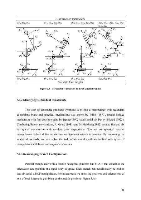
Construction Parameters<br />
a13, a24, a35 a13, a24, a35, α24 a13, a24, a35, a46, α35 a13, a24, a35, a46, a57,<br />
α24, α46<br />
E2<br />
E5<br />
θ24<br />
θ13<br />
E3 E4<br />
a35<br />
a24<br />
a13<br />
θ35<br />
E1<br />
E6<br />
θ13, θ24, θ35 θ13, θ35, θ46 θ13, θ24, θ46 θ13, θ35, θ57<br />
Variable Joint Angles<br />
Figure 3.3 – Structural synthesis <strong>of</strong> an RRR kinematic chain.<br />
3.4.2 Identifying Redundant Constraints<br />
This step <strong>of</strong> kinematic structural synthesis is to find a manipulator with redundant<br />
constraints. Plane <strong>and</strong> spherical mechanisms was shown by Willis (1870), spatial linkage<br />
mechanism with four revolute pairs by Bennet (1903) <strong>and</strong> spatial six-bar by Bricard (1923).<br />
Combining Bennet mechanisms, F. Myard (1931) <strong>and</strong> M. Goldberg(1943) created five <strong>and</strong> six<br />
bar spatial mechanisms with revolute pairs respectively. Now we use spherical parallel<br />
manipulators, spherical five or six link manipulators widely in practice. By improving the<br />
analytical methods, we can solve the task <strong>of</strong> structural synthesis to find new types <strong>of</strong><br />
manipulators with linear <strong>and</strong> angular constraints.<br />
3.4.3 Rearranging Branch Configurations<br />
E2<br />
E6 E7<br />
α24<br />
θ13<br />
E3<br />
a35<br />
a24<br />
a13<br />
θ35<br />
a46<br />
E1<br />
θ46<br />
E4<br />
E5<br />
Parallel manipulator with a mobile hexagonal platform has 6 DOF that describes the<br />
orientation <strong>and</strong> position <strong>of</strong> a rigid body in space. Each branch can conditionally be broken<br />
into six serial 6 DOF manipulators. For inverse task we know the positions <strong>and</strong> orientations <strong>of</strong><br />
axis <strong>of</strong> each kinematic pair lying on the mobile platform (Figure 3.4a).<br />
E2<br />
θ13<br />
E5<br />
E3<br />
a24<br />
E7<br />
a13<br />
a46<br />
a35<br />
E1<br />
E6<br />
θ24<br />
θ46<br />
α35<br />
E4<br />
E6<br />
E2<br />
E8<br />
θ13<br />
α24<br />
E3<br />
θ57<br />
a35<br />
a24<br />
a13<br />
a57<br />
θ35<br />
E7<br />
a46<br />
E1<br />
E4<br />
E5<br />
α46<br />
34


