Kinematic and Dynamic Analysis of Spatial Six Degree of Freedom ...
Kinematic and Dynamic Analysis of Spatial Six Degree of Freedom ...
Kinematic and Dynamic Analysis of Spatial Six Degree of Freedom ...
You also want an ePaper? Increase the reach of your titles
YUMPU automatically turns print PDFs into web optimized ePapers that Google loves.
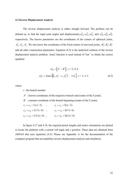
4.3 Inverse Displacement <strong>Analysis</strong><br />
The inverse displacement analysis is rather straight forward. The problem can be<br />
defined as, to find the input joint angles <strong>and</strong> displacements, α , α , α <strong>and</strong><br />
1<br />
13<br />
3<br />
13<br />
5<br />
13<br />
a<br />
2<br />
35<br />
4<br />
35<br />
, a , a<br />
respectively. The known parameters are the coordinates <strong>of</strong> the centers <strong>of</strong> spherical joints,<br />
v<br />
x<br />
v<br />
y<br />
v<br />
z<br />
A , A , A . We also know the coordinates <strong>of</strong> the fixed centers <strong>of</strong> universal joints, B , B , B<br />
<strong>and</strong> all other construction parameters. Equation (4.5) is the analytical solution <strong>of</strong> the inverse<br />
displacement analysis problem. Atan2 function is used instead <strong>of</strong> Tan -1 to obtain the correct<br />
quadrant.<br />
where<br />
v<br />
13<br />
v : the branch number<br />
v<br />
35<br />
v<br />
a = A − B<br />
v<br />
, v = 2, 4, 6<br />
v v v<br />
[ ( s A − c A ) , 2A<br />
]<br />
α = Atan 2<br />
, v = 1, 3, 5 (4.5)<br />
v<br />
x<br />
v<br />
v<br />
A : known coordinates <strong>of</strong> the respective branch end (center <strong>of</strong> the S joint).<br />
v<br />
B : constant coordinate <strong>of</strong> the branch beginning (center <strong>of</strong> the U joint).<br />
c = c = C( π / 2)<br />
, s = s = S( π / 2)<br />
1<br />
2<br />
c = c = C( 7π<br />
/ 6)<br />
, s = s = S( 7π<br />
/ 6)<br />
3<br />
4<br />
c = c = C( 11π<br />
/ 6)<br />
, s = s = S( 11π<br />
/ 6)<br />
5<br />
6<br />
1<br />
3<br />
5<br />
2<br />
4<br />
6<br />
In figure 4.17 <strong>and</strong> 4.18, the required piston lengths <strong>and</strong> motor orientations are plotted<br />
to locate the platform with a certain roll angle <strong>and</strong> z position. These data are obtained from<br />
iMIDAS that uses equations (4.5). Please see Appendix A for the documentation <strong>of</strong> the<br />
computer program that accomplishes inverse displacement analysis <strong>and</strong> simulation.<br />
y<br />
z<br />
v<br />
x<br />
v<br />
y<br />
6<br />
35<br />
v<br />
z<br />
52


