

Kinematic and Dynamic Analysis of Spatial Six Degree of Freedom ...
Kinematic and Dynamic Analysis of Spatial Six Degree of Freedom ...
Kinematic and Dynamic Analysis of Spatial Six Degree of Freedom ...

You also want an ePaper? Increase the reach of your titles
YUMPU automatically turns print PDFs into web optimized ePapers that Google loves.
The best way <strong>of</strong> visualizing the discrepancies between two solutions is to plot the<br />
graphs <strong>of</strong> corresponding data. However for the parallel manipulator, there are six input<br />
variables <strong>and</strong> six output variables, for which there isn’t a convenient way to show all data in a<br />
single graph. For this reason the orientation <strong>and</strong> location <strong>of</strong> the platform center are plotted on<br />
separate sheets. Also for the cases where two or more actuators are used simultaneously, the<br />
values <strong>of</strong> those are set equal (i.e. linear speeds <strong>of</strong> pistons are the same where as the angular<br />
velocities <strong>of</strong> the motors are the same). Finally for comparison <strong>of</strong> the results, the main criterion<br />
used is the distance <strong>of</strong> the platform centroid from the origin.<br />
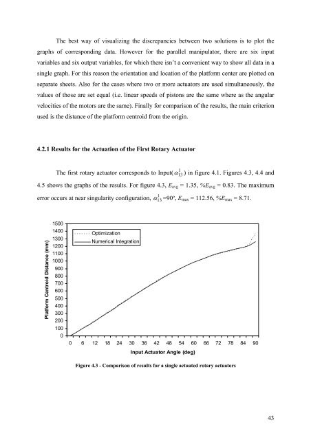
4.2.1 Results for the Actuation <strong>of</strong> the First Rotary Actuator<br />
The first rotary actuator corresponds to Input( α ) in figure 4.1. Figures 4.3, 4.4 <strong>and</strong><br />
4.5 shows the graphs <strong>of</strong> the results. For figure 4.3, Eavg = 1.35, %Eavg = 0.83. The maximum<br />
error occurs at near singularity configuration,<br />
Platform Centroid Distance (mm)<br />
1500<br />
1400<br />
1300<br />
1200<br />
1100<br />
1000<br />
900<br />
800<br />
700<br />
600<br />
500<br />
400<br />
300<br />
200<br />
100<br />
0<br />
Optimization<br />
Numerical Integration<br />
1<br />
13<br />
1<br />
α 13 =90º, Emax = 112.56, %Emax = 8.71.<br />
0 6 12 18 24 30 36 42 48 54 60 66 72 78 84 90<br />
Input Actuator Angle (deg)<br />
Figure 4.3 - Comparison <strong>of</strong> results for a single actuated rotary actuators<br />
43


