Using the FONIX 7000 to Verify Coupler and Real-Ear Performance ...
Using the FONIX 7000 to Verify Coupler and Real-Ear Performance ...
Using the FONIX 7000 to Verify Coupler and Real-Ear Performance ...

Create successful ePaper yourself
Turn your PDF publications into a flip-book with our unique Google optimized e-Paper software.
<strong>Coupler</strong> Measurements 25<br />
Note… The use of <strong>the</strong> continuous pure-<strong>to</strong>ne bias signal (available in 100 Hz increments) acting<br />
as a noise source presented simultaneously with <strong>the</strong> modulated speech composite signal allows<br />
<strong>the</strong> clinician <strong>to</strong> more effectively verify <strong>the</strong> effectiveness of <strong>the</strong> noise reduction feature of <strong>the</strong><br />
hearing aid in reducing <strong>the</strong> gain/output only in <strong>the</strong> frequency region surrounding <strong>the</strong> distracting<br />
noise while leaving intact <strong>the</strong> frequency region above <strong>and</strong> below <strong>the</strong> distracting noise. This,<br />
<strong>the</strong>oretically, would result in improved communication <strong>and</strong> comfort in noise because <strong>the</strong><br />
reduction in gain will be in a restricted segment of <strong>the</strong> frequency response instead of a larger<br />
segment of <strong>the</strong> frequency response in response <strong>to</strong> a noise. It is believed that hearing aids with<br />
greater channels of noise reduction could lead <strong>to</strong> better performance in noise (<strong>and</strong> feedback<br />
management) because in multichannel aids narrower <strong>and</strong> narrower segments of <strong>the</strong> frequency<br />
response are reduced in response <strong>to</strong> noise (or feedback) within <strong>the</strong> environment.<br />
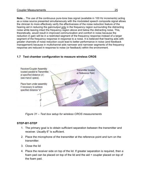
1.7 Test chamber configuration <strong>to</strong> measure wireless CROS<br />
Figure 31 – Test box setup for wireless CROS measurements<br />
STEP-BY-STEP<br />
1. The primary goal is <strong>to</strong> obtain sufficient separation between <strong>the</strong> transmitter <strong>and</strong><br />
receiver. Usually 6” is sufficient.<br />
2. Place <strong>the</strong> microphone of <strong>the</strong> transmitter at <strong>the</strong> reference point <strong>and</strong> turn on <strong>the</strong><br />
transmitter.<br />
3. Close <strong>the</strong> lid<br />
4. Place <strong>the</strong> receiver side on <strong>to</strong>p of <strong>the</strong> lid. If greater separation is required, <strong>the</strong>n a<br />
foam pad can be placed on <strong>to</strong>p of <strong>the</strong> lid <strong>and</strong> <strong>the</strong> aid + coupler placed on <strong>to</strong>p of<br />
<strong>the</strong> foam pad.