Ergonomics - Atlas Copco
Ergonomics - Atlas Copco
Ergonomics - Atlas Copco

You also want an ePaper? Increase the reach of your titles
YUMPU automatically turns print PDFs into web optimized ePapers that Google loves.
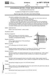
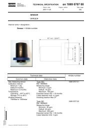
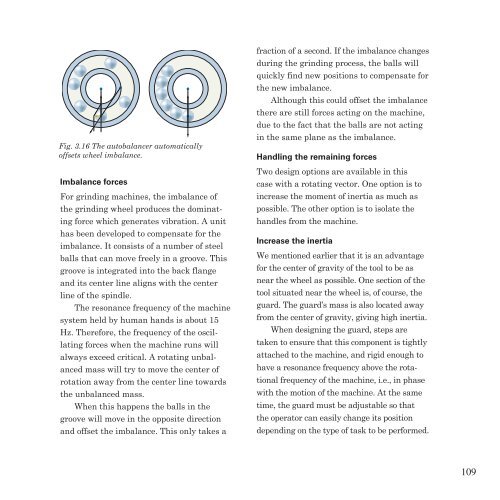
Fig. 3.16 The autobalancer automatically<br />
offsets wheel imbalance.<br />
Imbalance forces<br />
For grinding machines, the imbalance of<br />
the grinding wheel produces the dominat-<br />
ing force which generates vibration. A unit<br />
has been developed to compensate for the<br />
imbalance. It consists of a number of steel<br />
balls that can move freely in a groove. This<br />
groove is integrated into the back flange<br />
and its center line aligns with the center<br />
line of the spindle.<br />
The resonance frequency of the machine<br />
system held by human hands is about 15<br />
Hz. Therefore, the frequency of the oscil-<br />
lating forces when the machine runs will<br />
always exceed critical. A rotating unbal-<br />
anced mass will try to move the center of<br />
rotation away from the center line towards<br />
the unbalanced mass.<br />
When this happens the balls in the<br />
groove will move in the opposite direction<br />
and offset the imbalance. This only takes a<br />
fraction of a second. If the imbalance changes<br />
during the grinding process, the balls will<br />
quickly find new positions to compensate for<br />
the new imbalance.<br />
Although this could offset the imbalance<br />
there are still forces acting on the machine,<br />
due to the fact that the balls are not acting<br />
in the same plane as the imbalance.<br />
Handling the remaining forces<br />
Two design options are available in this<br />
case with a rotating vector. One option is to<br />
increase the moment of inertia as much as<br />
possible. The other option is to isolate the<br />
handles from the machine.<br />
Increase the inertia<br />
We mentioned earlier that it is an advantage<br />
for the center of gravity of the tool to be as<br />
near the wheel as possible. One section of the<br />
tool situated near the wheel is, of course, the<br />
guard. The guard’s mass is also located away<br />
from the center of gravity, giving high inertia.<br />
When designing the guard, steps are<br />
taken to ensure that this component is tightly<br />
attached to the machine, and rigid enough to<br />
have a resonance frequency above the rota-<br />
tional frequency of the machine, i.e., in phase<br />
with the motion of the machine. At the same<br />
time, the guard must be adjustable so that<br />
the operator can easily change its position<br />
depending on the type of task to be performed.<br />
109