analysis of a pilot-scale anaerobic baffled reactor treating domestic ...
analysis of a pilot-scale anaerobic baffled reactor treating domestic ...
analysis of a pilot-scale anaerobic baffled reactor treating domestic ...

You also want an ePaper? Increase the reach of your titles
YUMPU automatically turns print PDFs into web optimized ePapers that Google loves.
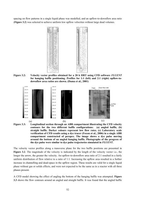
spacing on flow patterns in a single liquid phase was modelled, and an upflow-to-downflow area ratio<br />
(Figure 3.2) was selected to achieve uniform low upflow velocities without large dead volumes.<br />
Figure 3.2: Velocity vector pr<strong>of</strong>iles obtained for a 20 h HRT using CFD s<strong>of</strong>tware FLUENT<br />
for hanging baffle positioning. Pr<strong>of</strong>iles for 1:1 (left) and 2:1 (right) upflow-todownflow<br />
area ratios are shown. (Dama et al., 2001)<br />
(a) (b)<br />
(c)<br />
Figure 3.3: Longitudinal section through an ABR compartment illustrating the CFD velocity<br />
contours for the two different baffle configurations: (a) angled baffle, (b)<br />
straight baffle. Darker colours represent low flow rates. (c) Laboratory <strong>scale</strong><br />
verification <strong>of</strong> CFD results using a dye tracer (Foxon et al., 2006) in a single ABR<br />
compartment constructed <strong>of</strong> perspex. The image shows a dye pulse moving<br />
around the bottom <strong>of</strong> an angled hanging baffle. Photographs <strong>of</strong> the progress <strong>of</strong><br />
the dye pulse were similar to dye pulse trajectories simulated in FLUENT.<br />
The velocity vector pr<strong>of</strong>iles along a transverse plane for the two baffle positions are presented in<br />
Figure 3.2. The magnitude <strong>of</strong> the velocity is indicated by the length <strong>of</strong> the velocity vector i.e., the<br />
longer the arrow, the greater the velocity. An upflow-to-downflow area ratio <strong>of</strong> 2:1 resulted in a fairly<br />
uniform distribution <strong>of</strong> flow relative to a ratio <strong>of</strong> 1:1. Increasing the upflow area resulted in a further<br />
increase in channelling and dead-space in the upflow region. These results are valid for a single liquid<br />
phase without gas or solids effects, and were not expected to be the same as in a <strong>reactor</strong> with all three<br />
phases present.<br />
A CFD model showing the effect <strong>of</strong> angling the bottom <strong>of</strong> the hanging baffle was attempted. Figure<br />
3.3 shows the flow contours around an angled and straight baffle. It was found that the angled baffle<br />
52<br />
Feed Down-flow side<br />
Dye<br />
pulse<br />
up-flow<br />
side