analysis of a pilot-scale anaerobic baffled reactor treating domestic ...
analysis of a pilot-scale anaerobic baffled reactor treating domestic ...
analysis of a pilot-scale anaerobic baffled reactor treating domestic ...

Create successful ePaper yourself
Turn your PDF publications into a flip-book with our unique Google optimized e-Paper software.
esulted in more even flow distribution and reduced dead-space. CFD tests were visually reproduced<br />
using a single compartment laboratory-<strong>scale</strong> ABR and dye in water (Figure 3.3 c).<br />
The Fluent simulations were used to assist in selection <strong>of</strong> design features <strong>of</strong> the baffles. They were not<br />
intended to be used in prediction <strong>of</strong> flow patterns in an ABR <strong>treating</strong> <strong>domestic</strong> wastewater since the<br />
presence <strong>of</strong> two additional phases (solid and gas) can substantially alter flow patterns, as compared to<br />
clean water flow patterns.<br />
3.1.1.1 Construction <strong>of</strong> <strong>reactor</strong><br />
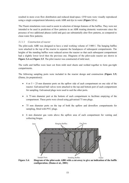
The <strong>pilot</strong>-<strong>scale</strong> ABR was designed to have a total working volume <strong>of</strong> 3 000 ℓ. The hanging baffles<br />
were attached to the top <strong>of</strong> the <strong>reactor</strong> to separate the headspaces <strong>of</strong> subsequent compartments. The<br />
heights <strong>of</strong> the standing baffles were reduced across the <strong>reactor</strong> so that each subsequent compartment<br />
had a slightly lower level then the previous one. Diagrams <strong>of</strong> the <strong>pilot</strong>-<strong>scale</strong> <strong>reactor</strong> are shown in<br />
Figure 3.4 and Figure 3.5. The <strong>pilot</strong> <strong>reactor</strong> was constructed <strong>of</strong> mild steel.<br />
The walls and baffles were laser cut from mild steel sheets and welded together to form gas-tight<br />
compartments.<br />
The following sampling ports were included in the <strong>reactor</strong> design and construction (Figure 3.5)<br />
(Dama, (in preparation)):<br />
• 4 or 5 × 25 mm diameter ports on the upflow side <strong>of</strong> each compartment on one side <strong>of</strong> the<br />
<strong>reactor</strong>. Galvanised ball valves were attached to the top and bottom port <strong>of</strong> each compartment<br />
for sampling. Galvanised plugs were used to seal the other ports.<br />
• A 75 mm diameter port at the bottom <strong>of</strong> each compartment to facilitate emptying <strong>of</strong> the<br />
compartment. These ports were closed using galvanised 75 mm plugs.<br />
• 75 mm diameter ports on the top <strong>of</strong> both the upflow and downflow compartments for<br />
sampling, fitted with PVC plugs.<br />
• 6 mm diameter gas vents above the upflow area <strong>of</strong> each compartment for venting and<br />
collecting biogas.<br />
Inlet<br />
Sample Ports<br />
Hanging Baffles<br />
Figure 3.4: Diagram <strong>of</strong> the <strong>pilot</strong>-<strong>scale</strong> ABR with a cut-away to give an indication <strong>of</strong> the baffle<br />
configuration. (Dama et al., 2001)<br />
53<br />
Gas Ports<br />
Standing Baffles Outlet