- Page 1 and 2:
Remote Sensing for Wind Energy DTU
- Page 3 and 4:
Author: Alfredo Peña, Charlotte B.
- Page 5 and 6:
4 Introduction to continuous-wave D
- Page 7 and 8:
8 Nacelle-based lidar systems 157 8
- Page 9 and 10:
12 Complex terrain and lidars 231 1
- Page 11 and 12:
1 Remote sensing of wind Torben Mik
- Page 13 and 14:
Figure 2: Calibration, laboratory w
- Page 15 and 16:
Figure 3: Example of scatter plots
- Page 17 and 18:
1.2.3 Summary of sodars Most of tod
- Page 19 and 20:
1.3.3 Wind lidars Measuring wind wi
- Page 21 and 22:
Figure 6: CW wind lidars (ZephIRs)
- Page 23 and 24:
Further developments Furthermore, n
- Page 25 and 26:
2 The atmospheric boundary layer S
- Page 27 and 28:
Figure 9: Large spatial scale varia
- Page 29 and 30:
Du3 Dt Du1 Dt Du2 Dt The three mome
- Page 31 and 32:
Figure 13: Consensus relations betw
- Page 33 and 34:
ψ z L ∼ − 5 L . For unstable c
- Page 35 and 36:
Figure 15: Behavior of the turbulen
- Page 37 and 38:
Figure 17: Newly developed models t
- Page 39 and 40:
The value of q0 at the surface is d
- Page 41 and 42:
the spray is the source of icing on
- Page 43 and 44:
u∗2 u∗1 u1(h) = u∗1 k ln h
- Page 45 and 46:
Figure 26:Land-seabreeze system,whe
- Page 47 and 48:
Figure28:Three dimensionalpicture o
- Page 49 and 50:
sufficient information. Finally, we
- Page 51 and 52:
Mann, J. (1998) Wind field simulati
- Page 53 and 54:
(2010) and comparison under differe
- Page 55 and 56:
To get the velocity field from the
- Page 57 and 58:
τ(k) [Arbitrary units] 10 3 10 2 1
- Page 59 and 60:
(Koopmans, 1974; Bendat and Piersol
- Page 61 and 62:
anemometer was installed at each en
- Page 63 and 64:
and fSw(f) u 2 ∗ = 1.05n 1+5.3n 5
- Page 65 and 66:
and n = 0.468. This spectrum implie
- Page 67 and 68:
to be calculated. We do that on a m
- Page 69 and 70:
Notation A Charnock constant neutra
- Page 71 and 72:
Maxey M. R. (1982) Distortion of tu
- Page 73 and 74:
4.2 Basic principles of lidar opera
- Page 75 and 76:
4.2.5 Wind profiling in conical sca
- Page 77 and 78:
4.3.1 Behaviour of scattering parti
- Page 79 and 80:
the beam radius at the output lens.
- Page 81 and 82:
from which the value of VLOS is der
- Page 83 and 84:
the atmosphere. The SNR 4 for a win
- Page 85 and 86:
individual line-of-sight wind speed
- Page 87 and 88:
A general approach to mitigating th
- Page 89 and 90:
from ±VH sinδ (if the tilt is tow
- Page 91 and 92:
as a down draught (of the same abso
- Page 93 and 94:
Table 7: Combined results from 28 Z
- Page 95 and 96: in Eastern Jutland between January
- Page 97 and 98: Figure 56: Normalized power curves
- Page 99 and 100: the concept. Developments include i
- Page 101 and 102: References x horizontal position in
- Page 103 and 104: Wagner R., Mikkelsen T., and Courtn
- Page 105 and 106: 5.2 End-to-end description of pulse
- Page 107 and 108: Scanner Coherent lidar measure the
- Page 109 and 110: Figure 62: Radial wind velocity ret
- Page 111 and 112: transform in order to use data obta
- Page 113 and 114: This wavelength is also the most fa
- Page 115 and 116: Eq.(132)isadaptedforcollimatedsyste
- Page 117 and 118: 5.3.6 Existing systems and actual p
- Page 119 and 120: (Gottshall et al., 2010; Albers et
- Page 121 and 122: References Albers A., Janssen A. W.
- Page 123 and 124: derived from fluctuations of the wi
- Page 125 and 126: Acoustic received echo (ARE) method
- Page 127 and 128: Figure 71: Sample time-height cross
- Page 129 and 130: A gradient minimum is characterized
- Page 131 and 132: Figure73:Bragg-relatedacoustic(belo
- Page 133 and 134: stability (inversion strength) can
- Page 135 and 136: Figure 76: Combined soundingwith a
- Page 137 and 138: Figure 79: Favorite regions (shaded
- Page 139 and 140: Direct detection of MLH from acoust
- Page 141 and 142: Engelbart D.A.M.and Bange J. (2002)
- Page 143 and 144: 7 What can remote sensing contribut
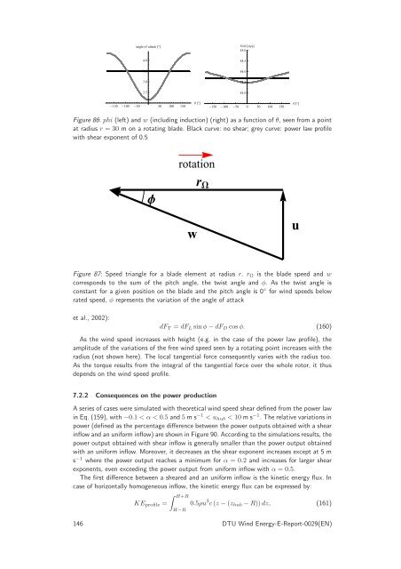
- Page 145: uyms 9.0 8.5 8.0 7.5 7.0 120 140 16
- Page 149 and 150: Height Height Hub 1.6 1.4 1.2 1.0 0
- Page 151 and 152: PP rated PP rated 1.0 0.8 0.6 0.4 0
- Page 153 and 154: KEprofileKEhub 1.2 1.1 1.0 0.9 0.8
- Page 155 and 156: PP rated WS Lidarms 1.0 0.8 0.6 0.4
- Page 157 and 158: 8 Nacelle-based lidar systems Andre
- Page 159 and 160: • Flexibletrajectories.Dependingo
- Page 161 and 162: Figure 104: Sketch of simultaneous
- Page 163 and 164: The normal wind direction vector nw
- Page 165 and 166: Figure 109: Test site at DTU Wind E
- Page 167 and 168: Figure 112: Power curve met mast an
- Page 169 and 170: Notation C number of sent photons C
- Page 171 and 172: 9 Lidars and wind turbine control -
- Page 173 and 174: for three unknowns, it is impossibl
- Page 175 and 176: model of the blade pitch actuator,
- Page 177 and 178: |GRL| [-] 1 0.8 0.6 0.4 0.2 10 k [r
- Page 179 and 180: PSD(Ωg) [(rpm) 2 /Hz] PSD(Ωg) [
- Page 181 and 182: 0.04 0.03 ˆk [ rad m ] 0.02 0.63 0
- Page 183 and 184: [%] 10 0 −10 −20 −30 MyT Moop
- Page 185 and 186: PSD(θ1) [rad 2 /Hz] PSD(Moop1) [Nm
- Page 187 and 188: Pel/Pel,max [-] 1 0.98 0.96 0.94 0.
- Page 189 and 190: fL weighting function GRL transfer
- Page 191 and 192: E. Hau, Windkraftanlagen, 4th ed. S
- Page 193 and 194: ¨¦¦§©¡§ ¥§¨¦¦§£ ¡¥
- Page 195 and 196: vertical (m) 150 100 50 R d 0
- Page 197 and 198:
With feedback only, on the other ha
- Page 199 and 200:
Figure 136: Estimated preview requi
- Page 201 and 202:
Normalized C r = C r P Q 2 W (r) b
- Page 203 and 204:
Normalized C r = C r P Q 2 W (r) b
- Page 205 and 206:
Coherence 1 0.8 0.6 0.4 0.2 0 10
- Page 207 and 208:
Coherence 1 0.8 0.6 0.4 0.2 0 10
- Page 209 and 210:
Magnitude Squared 10 8 10 7 10 6 10
- Page 211 and 212:
Figure 148: During simulation, FAST
- Page 213 and 214:
Figure 149: Collective flap respons
- Page 215 and 216:
Magnitude (abs) blade pitch gen spe
- Page 217 and 218:
• Measurement coherence, which ca
- Page 219 and 220:
Jonkman, B. (2009) TurbSim user’s
- Page 221 and 222:
11 Lidars and wind profiles Alfredo
- Page 223 and 224:
z [m] 160 100 80 60 40 20 10 15 20
- Page 225 and 226:
z [−] zo 1 κ ln 40 38 36 34 32 3
- Page 227 and 228:
z [m] z [m] 1000 900 800 700 600 50
- Page 229 and 230:
the growth of the length scale, agr
- Page 231 and 232:
12 Complex terrain and lidars Ferha
- Page 233 and 234:
Figure 158: The ZephIR models which
- Page 235 and 236:
Uconst wΑx l h Φ h.tanΦ Figure 1
- Page 237 and 238:
Figure 162: Lavrio: The scatter plo
- Page 239 and 240:
Figure 163: Panahaiko: The scatter
- Page 241 and 242:
References Albers A. and Janssen A.
- Page 243 and 244:
Wexler (1968), where the limitation
- Page 245 and 246:
13.2.1 Systematic turbulence errors
- Page 247 and 248:
where x is the center of the scanni
- Page 249 and 250:
The theoretical systematic errors a
- Page 251 and 252:
Height (m) 160 140 120 100 80 60 40
- Page 253 and 254:
Height (m) Height (m) 160 140 120 1
- Page 255 and 256:
RMSPE (%) 70 60 50 40 30 20 10 0 vu
- Page 257 and 258:
involves interaction of all compone
- Page 259 and 260:
Lindelöw P. (2007) Fibre Based Coh
- Page 261 and 262:
plications, including meteorologica
- Page 263 and 264:
Figure 173: Rayleigh-Jeans’ appro
- Page 265 and 266:
Figure 176: Brightness temperature
- Page 267 and 268:
with rain are shown in Fig. 179. A
- Page 269 and 270:
This method gives a good accuracy (
- Page 271 and 272:
Figure 183: A recent maintenance in
- Page 273 and 274:
Figure 185: Temperature profiles in
- Page 275 and 276:
References s point in space Sν(s)
- Page 277 and 278:
Also the Doppler Centroid anomaly c
- Page 279 and 280:
Christiansen et al., 2006). The res
- Page 281 and 282:
educe speckle noise, a random noise
- Page 283 and 284:
Figure 188: Envisat ASAR wind field
- Page 285 and 286:
Figure 190: Envisat ASAR wind field
- Page 287 and 288:
Satellites in sun-synchronous polar
- Page 289 and 290:
500 overlapping scenes for wind res
- Page 291 and 292:
(with the fewest samples). The unce
- Page 293 and 294:
Badger M., Hasager C. B., Thompson
- Page 295 and 296:
Ren Y. Z., Lehner S., Brusch S., Li
- Page 297 and 298:
tracking, climate studies, air-sea
- Page 299 and 300:
The modified logarithmic wind profi
- Page 301 and 302:
sea ice mask was applied and σ0 me
- Page 303 and 304:
QuikSCAT 25 20 15 10 5 Horns Rev Fi
- Page 305 and 306:
Figure 203:Example of an ASCAT coas
- Page 307 and 308:
References Bourassa M.A., Legler D.
- Page 309:
DTU Wind Energy Technical Universit