

Publishers version - DTU Orbit
Publishers version - DTU Orbit
Publishers version - DTU Orbit

You also want an ePaper? Increase the reach of your titles
YUMPU automatically turns print PDFs into web optimized ePapers that Google loves.
10 Lidars and wind turbine control –<br />
Part 2<br />
Eric Simley 1 , Fiona Dunne 1 , Jason Laks 2 , and Lucy Y. Pao 1<br />
1 Department of Electrical, Computer, and Energy Engineering, University of<br />
Colorado, Boulder, CO, USA<br />
2 National Renewable Energy Laboratory, Golden, CO, USA<br />
10.1 Introduction<br />
Modern utility-scale wind turbines are typically controlled using yaw, generator torque, and<br />
blade pitch actuation (Pao and Johnson, 2011). The yaw motor is used to align the rotor with<br />
thewinddirectionforthepurposeofmaximizingpowercapture.Generatortorqueiscontrolled<br />
duringbelow-rated(region2)operationtomaximizepowercapturebymaintainingtheoptimal<br />
tip speed ratio. In above-rated conditions (region 3), the blades are pitched to regulate rotor<br />
speed and power capture by limiting the amount of aerodynamic torque produced by the<br />
rotor. In addition to regulating rotor speed, region 3 control systems are often designed to<br />
reduce structural loads on the turbine caused by turbulence.<br />
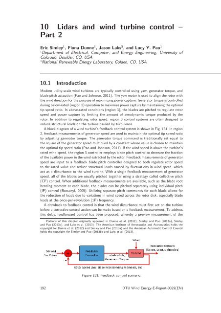
A block diagram of a wind turbine’s feedback control system is shown in Fig. 131. In region<br />
2, feedback measurements of generatorspeed are used to maintain the optimal tip speed ratio<br />
by adjusting generator torque. The generator torque command is traditionally set equal to<br />
the square of the generator speed multiplied by a constant whose value is chosen to maintain<br />
the optimal tip speed ratio (Pao and Johnson, 2011). If the wind speed is above the turbine’s<br />
rated wind speed, the region 3 controller employs blade pitch control to decrease the fraction<br />
oftheavailablepowerinthewindextracted bytherotor.Feedbackmeasurementsofgenerator<br />
speed are input to a feedback blade pitch controller designed to both regulate rotor speed<br />
to the rated value and reduce structural loads caused by fluctuations in wind speed, which<br />
act as a disturbance to the wind turbine. With a single feedback measurement of generator<br />
speed, all of the blades are usually pitched together using a strategy called collective pitch<br />
(CP) control. When additional feedback measurements are available, such as the blade root<br />
bending moment at each blade, the blades can be pitched separately using individual pitch<br />
(IP) control (Bossanyi, 2005). Utilizing separate pitch commands for each blade allows for<br />
the reduction of loads due to variations in wind speed across the rotor disk, especially blade<br />
loads at the once-per-revolution (1P) frequency.<br />
A drawback to feedback control is that the wind disturbance must first act on the turbine<br />
before a corrective control action can be made based on a feedback measurement. To address<br />
this delay, feedforward control has been proposed, whereby a preview measurement of the<br />
Portions of this chapter originally appeared in Dunne et al. (2012), Simley and Pao (2013a), Simley<br />
and Pao (2013b), and Laks et al. (2013). The American Institute of Aeronautics and Astronautics holds the<br />
copyright for Dunne et al. (2012) and Simley and Pao (2013a) and the American Automatic Control Council<br />
holds the copyright for Simley and Pao (2013b) and Laks et al. (2013).<br />
¡¡¢¨¤¢¡¡¥¨© ¡¡¢ ¡©¡¤¨¨¡ ¡¡¢£¤¥¦ ©¢<br />
Figure 131: Feedback control scenario.<br />
192 <strong>DTU</strong> Wind Energy-E-Report-0029(EN)<br />
£©¡ ¡¤¡¢<br />
¨¨¡¡¢¤©¢¤¢¡¨¨¡©¢©¨¡©¡¥ ¡¨© ¤¢¡¥ §¨©¨¡


