

Edwards IH Instruction Manual - Ideal Vacuum Products
Edwards IH Instruction Manual - Ideal Vacuum Products
Edwards IH Instruction Manual - Ideal Vacuum Products

You also want an ePaper? Increase the reach of your titles
YUMPU automatically turns print PDFs into web optimized ePapers that Google loves.
The status LEDs (9) show the current status of the iH system and the Pump Display Terminal:<br />
LED LED colour Meaning<br />
ALARM Red This LED shows when an alarm condition exists.<br />
WARNING Amber This LED shows when a warning condition exists.<br />
LOCAL<br />
CONTROL<br />
Green<br />
This LED is on when the Pump Display Terminal has control of the iH<br />
system.<br />
The ALARM and WARNING LEDs flash when the corresponding alarm or warning<br />
condition first occurs. When you acknowledge the condition (refer to Section 5.9), the<br />
corresponding LED goes on permanently. For most alarms and warnings, if the condition<br />
clears (that is, the fault which caused the condition is no longer present), the corresponding<br />
LED goes off; see Tables 6-1 and 6-2 for the warnings and alarms whose LEDs do not<br />
automatically reset in this way.<br />
If remote operation in excess of 25m is expected, a Pump Display Module should be used.<br />
The functionality of the Pump Display Module is the same as that of the Pump Display<br />
Terminal. Refer to Section 8.5.8 for ordering information.<br />
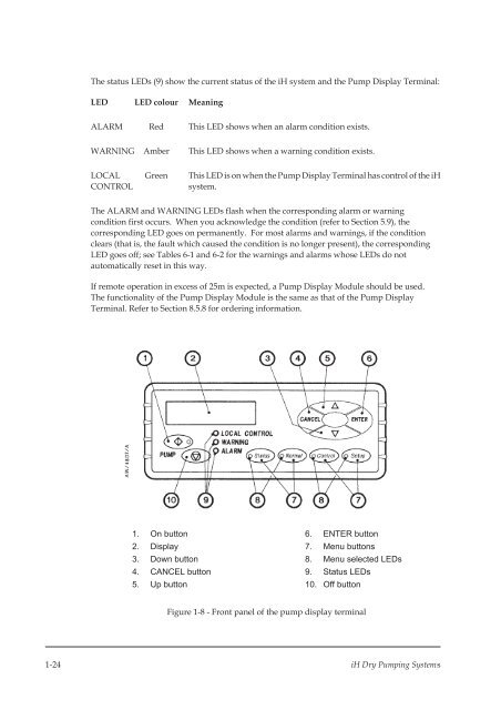
1. On button<br />
2. Display<br />
3. Down button<br />
4. CANCEL button<br />
5. Up button<br />
6. ENTER button<br />
7. Menu buttons<br />
8. Menu selected LEDs<br />
9. Status LEDs<br />
10. Off button<br />
Figure 1-8 - Front panel of the pump display terminal<br />
1-24 iH Dry Pumping Systems


