Edwards IH Instruction Manual - Ideal Vacuum Products
Edwards IH Instruction Manual - Ideal Vacuum Products
Edwards IH Instruction Manual - Ideal Vacuum Products
You also want an ePaper? Increase the reach of your titles
YUMPU automatically turns print PDFs into web optimized ePapers that Google loves.
• Connect an additional earth (ground) cable to the M6 RF earth (ground) stud. You must use a<br />
suitable low-impedance cable (for example, use braided cable).<br />
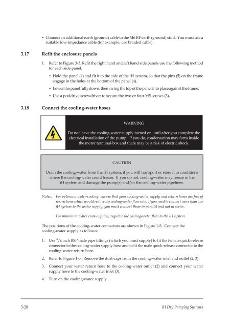
3.17 Refit the enclosure panels<br />
1. Refer to Figure 3-3. Refit the right hand and left hand side panels use the following method<br />
for each side panel.<br />
• Hold the panel (4) and fit it to the side of the iH system, so that the pins (5) on the frame<br />
engage in the holes at the bottom of the panel (4).<br />
• Lower the panel fully down, then swingthe top of the panel into place against the frame.<br />
• Use a posidrive screwdriver to secure the two or four M5 screws (3).<br />
3.18 Connect the cooling-water hoses<br />
WARNING<br />
Do not leave the cooling-water supply turned on until after you complete the<br />
electrical installation of the pump. If you do, condensation may form inside<br />
the motor terminal-box and there may be a risk of electric shock.<br />
CAUTION<br />
Drain the cooling-water from the iH system, if you will transport or store it in conditions<br />
where the cooling-water could freeze. If you do not, cooling-water may freeze in the<br />
iH system and damage the pump(s) and/or the cooling-water pipelines.<br />
Notes:<br />
For optimum water-cooling, ensure that your cooling-water supply andreturn hoses are free of<br />
restrictions which wouldreduce the cooling-water flow rate. If you needto connect more than one<br />
iH system to the water supply, you must connect them in parallel and not in series.<br />
For minimum water consumption, regulate the cooling-water flow to the iH system.<br />
The positions of the cooling-water connectors are shown in Figure 1-5. Connect the<br />
cooling-water supply as follows:<br />
1. Use 3 / 8 inch BSP male pipe fittings (which you must supply) to fit the female quick-release<br />
connector to the cooling-water supply hose and to fit the male quick-release connector to the<br />
cooling-water return hose.<br />
2. Refer to Figure 1-5. Remove the dust-caps from the cooling-water inlet and outlet (2, 3).<br />
3. Connect your water return hose to the cooling-water outlet (2) and connect your water<br />
supply hose to the cooling-water inlet (3).<br />
4. Turn on the cooling-water supply.<br />
3-28 iH Dry Pumping Systems


