

INSTALLATION MANUAL - Smarthome
INSTALLATION MANUAL - Smarthome
INSTALLATION MANUAL - Smarthome

Create successful ePaper yourself
Turn your PDF publications into a flip-book with our unique Google optimized e-Paper software.
Two-Wire Smoke Zones (Zone 16)<br />
To enable use of two-wire smoke detectors on Zone 16, position Jumper JP1 (located below Zone 16 terminals) so that the<br />
two right hand pins are covered. Go to Installer programming mode, Menu 05 - Zone Definitions, and program Zone 16 as a<br />
Fire zone (Def=10). Step to next location and program Wire Type=6. NOTE Use only compatible two-wire detectors listed on<br />
the front label of the control. Do not mix brands. The maximum number of detectors is also listed on the front label. For<br />
two-wire operation, a 820 Ohm EOL resistor part # ER820 must be used instead of the 2,200 Ohm resistor part # ER2200.<br />
Use 18AWG Fire approved wire. Max. wire length = 1000 feet. Max. wire resistance should not exceed 13 Ohms.<br />
Switched Power Connection (+SAUX)<br />
Four-wire smoke detector and other devices that require a temporary power disruption in order to reset or unlatch from the<br />
alarm state (i.e. smoke detectors, etc.) should be connected to the +SAUX 12 Volt DC switched power terminal. When a<br />
smoke reset is performed, the operating voltage to these devices is momentarily interrupted.<br />
Auxiliary Power Connections (+VAUX)<br />
Motion detectors, glass breaks, etc. and other devices requiring unswitched 24-hour power should be connected to one of the<br />
auxiliary terminals, +VAUX. All negative terminals on the terminal strip are at the same reference and may be used whenever<br />
a common (circuit ground) negative is required. Use caution when wiring the control to distribute the load devices among the<br />
supply and the negative terminals evenly. NOTE: Circuit ground refers to any negative terminal connection on this control.<br />
This does not refer to the earth ground terminal or to the common terminals of Relay Output 3. These terminals are not at<br />
the same voltage potential and should not be wired so that they are electrically connected to a negative.<br />
PTC (Positive Temperature Coefficient) Circuit Breakers<br />
The +VAUX Auxiliary power and J16 power output terminals are protected against shorts and overloads by a 1.25A PTC. A PTC<br />
is a solid state, auto-restoring type of circuit breaker. The +SAUX Switched (Smoke) power output is protected by a 1.1A PTC.<br />
The +VKP Keypad power output is protected by a 1.25A PTC. Output 2 is protected by a 1.25A PTC. NOTE: Sometimes it may<br />
be necessary to remove power (unplug the outputs) for approx. 20 seconds after a short, to allow the PTC to reset. Even<br />
if the short is no longer present, the remaining residual current draw may be so high that the PTC cannot determine that<br />
the short is gone. If the PTC re-trips, check the field wiring and repair.<br />
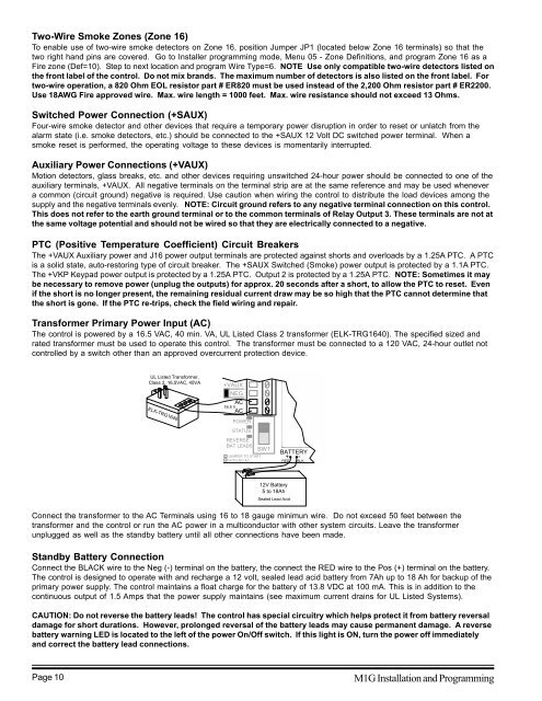
Transformer Primary Power Input (AC)<br />
The control is powered by a 16.5 VAC, 40 min. VA, UL Listed Class 2 transformer (ELK-TRG1640). The specified sized and<br />
rated transformer must be used to operate this control. The transformer must be connected to a 120 VAC, 24-hour outlet not<br />
controlled by a switch other than an approved overcurrent protection device.<br />
UL Listed Transformer,<br />
Class 2, 16.5VAC, 45VA<br />
ELK-TRG1640<br />
+VAUX<br />
NEG<br />
AC<br />
16.5 V<br />
AC<br />
POWER<br />
STATUS<br />
REVERSE<br />
BAT LEADS<br />
JUMPER TO START<br />
WITH NO AC<br />
SW1<br />
BATTERY<br />
+ -<br />
RED<br />
BLK<br />
+ -<br />
12V Battery<br />
5 to 18Ah<br />
Sealed Lead Acid<br />
Connect the transformer to the AC Terminals using 16 to 18 gauge minimun wire. Do not exceed 50 feet between the<br />
transformer and the control or run the AC power in a multiconductor with other system circuits. Leave the transformer<br />
unplugged as well as the standby battery until all other connections have been made.<br />
Standby Battery Connection<br />
Connect the BLACK wire to the Neg (-) terminal on the battery, the connect the RED wire to the Pos (+) terminal on the battery.<br />
The control is designed to operate with and recharge a 12 volt, sealed lead acid battery from 7Ah up to 18 Ah for backup of the<br />
primary power supply. The control maintains a float charge for the battery of 13.8 VDC at 100 mA. This is in addition to the<br />
continuous output of 1.5 Amps that the power supply maintains (see maximum current drains for UL Listed Systems).<br />
CAUTION: Do not reverse the battery leads! The control has special circuitry which helps protect it from battery reversal<br />
damage for short durations. However, prolonged reversal of the battery leads may cause permanent damage. A reverse<br />
battery warning LED is located to the left of the power On/Off switch. If this light is ON, turn the power off immediately<br />
and correct the battery lead connections.<br />
Page 10<br />
M1G Installation and Programming


