

INSTALLATION MANUAL - Smarthome
INSTALLATION MANUAL - Smarthome
INSTALLATION MANUAL - Smarthome

You also want an ePaper? Increase the reach of your titles
YUMPU automatically turns print PDFs into web optimized ePapers that Google loves.
Section 1 - Installation and Wiring<br />
1.1 Planning the Installation<br />
The first step in any multi-zone security system installation is planning the job.<br />
1. Read this entire manual to familiarize yourself with all system features and procedures before actually beginning the<br />
installation. Read all the information regarding Underwriters Laboratories (UL) and NFPA requirements.<br />
2. Perform a physical survey of the installation site. Use the diagrams below as a guide in planning the installation.<br />
3. Discuss the installation requirements and applications with the customer.<br />
4. Compare the installation requirements and applications with the factory default settings to determine what customized<br />
programming is needed to meet the specific installation requirements.<br />
5. Bench test the system prior to installation.<br />
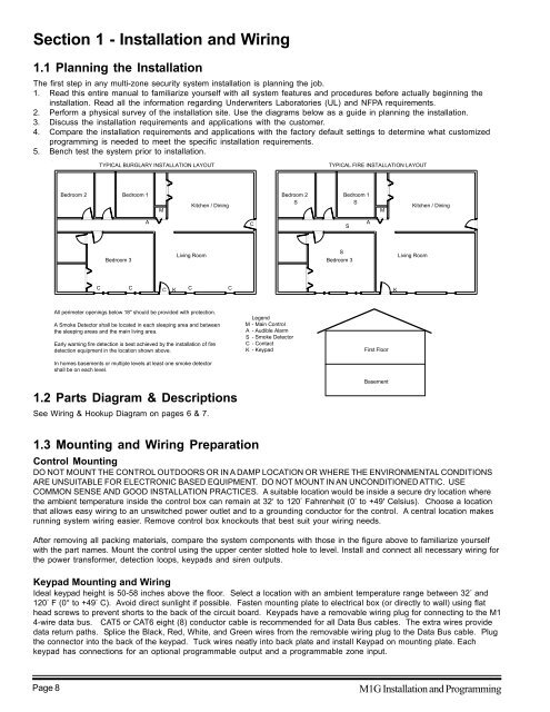
TYPICAL BURGLARY <strong>INSTALLATION</strong> LAYOUT<br />
TYPICAL FIRE <strong>INSTALLATION</strong> LAYOUT<br />
Bedroom 2<br />
Bedroom 1<br />
M<br />
Kitchen / Dining<br />
Bedroom 2<br />
S<br />
Bedroom 1<br />
S<br />
M<br />
Kitchen / Dining<br />
A<br />
C<br />
S<br />
A<br />
Bedroom 3<br />
Living Room<br />
S<br />
Bedroom 3<br />
Living Room<br />
C<br />
C<br />
C<br />
K<br />
C<br />
C<br />
K<br />
All perimeter openings below 18" should be provided with protection.<br />
A Smoke Detector shall be located in each sleeping area and between<br />
the sleeping areas and the main living area.<br />
Early warning fire detection is best achieved by the installation of fire<br />
detection equipment in the location shown above.<br />
In homes basements or multiple levels at least one smoke detector<br />
shall be on each level.<br />
1.2 Parts Diagram & Descriptions<br />
See Wiring & Hookup Diagram on pages 6 & 7.<br />
Legend<br />
M - Main Control<br />
A - Audible Alarm<br />
S - Smoke Detector<br />
C - Contact<br />
K - Keypad<br />
First Floor<br />
Basement<br />
1.3 Mounting and Wiring Preparation<br />
Control Mounting<br />
DO NOT MOUNT THE CONTROL OUTDOORS OR IN A DAMP LOCATION OR WHERE THE ENVIRONMENTAL CONDITIONS<br />
ARE UNSUITABLE FOR ELECTRONIC BASED EQUIPMENT. DO NOT MOUNT IN AN UNCONDITIONED ATTIC. USE<br />
COMMON SENSE AND GOOD <strong>INSTALLATION</strong> PRACTICES. A suitable location would be inside a secure dry location where<br />
the ambient temperature inside the control box can remain at 32‘ to 120 ° Fahrenheit (0’ to +49' Celsius). Choose a location<br />
that allows easy wiring to an unswitched power outlet and to a grounding conductor for the control. A central location makes<br />
running system wiring easier. Remove control box knockouts that best suit your wiring needs.<br />
After removing all packing materials, compare the system components with those in the figure above to familiarize yourself<br />
with the part names. Mount the control using the upper center slotted hole to level. Install and connect all necessary wiring for<br />
the power transformer, detection loops, keypads and siren outputs.<br />
Keypad Mounting and Wiring<br />
Ideal keypad height is 50-58 inches above the floor. Select a location with an ambient temperature range between 32 ° and<br />
120 ° F (0° to +49 ° C). Avoid direct sunlight if possible. Fasten mounting plate to electrical box (or directly to wall) using flat<br />
head screws to prevent shorts to the back of the circuit board. Keypads have a removable wiring plug for connecting to the M1<br />
4-wire data bus. CAT5 or CAT6 eight (8) conductor cable is recommended for all Data Bus cables. The extra wires provide<br />
data return paths. Splice the Black, Red, White, and Green wires from the removable wiring plug to the Data Bus cable. Plug<br />
the connector into the back of the keypad. Tuck wires neatly into back plate and install Keypad on mounting plate. Each<br />
keypad has connections for an optional programmable output and a programmable zone input.<br />
Page 8<br />
M1G Installation and Programming


