

INSTALLATION MANUAL - Smarthome
INSTALLATION MANUAL - Smarthome
INSTALLATION MANUAL - Smarthome

You also want an ePaper? Increase the reach of your titles
YUMPU automatically turns print PDFs into web optimized ePapers that Google loves.
1234567890123456789012345<br />
1234567890123456789012345<br />
1234567890123456789012345<br />
1234567890123456789012345<br />
1234567890123456789012345<br />
1234567890123456789012345<br />
1234567890123456789012345<br />
1234567890123456789012345<br />
1234567890123456789012345<br />
1234567890123456789012345<br />
1234567890123456789012345<br />
1234567890123456789012345<br />
1234567890123456789012345<br />
1234567890123456789012345<br />
1234567890123456789012345<br />
1234567890123456789012345<br />
1234567890123456789012345<br />
1234567890123456789012345<br />
1234567890123456789012345<br />
1234567890123456789012345<br />
1234567890123456789012345<br />
1234567890123456789012345<br />
1234567890123456789012345<br />
1234567890123456789012345<br />
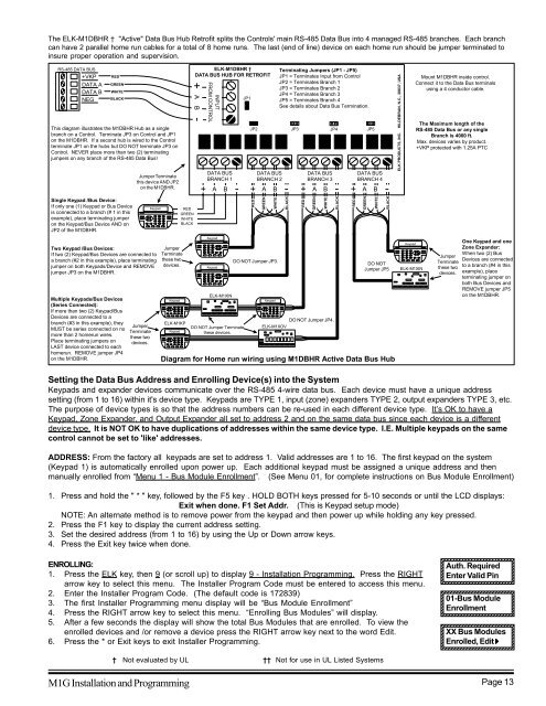
The ELK-M1DBHR † "Active" Data Bus Hub Retrofit splits the Controls' main RS-485 Data Bus into 4 managed RS-485 branches. Each branch<br />
can have 2 parallel home run cables for a total of 8 home runs. The last (end of line) device on each home run should be jumper terminated to<br />
insure proper operation and supervision.<br />
RS-485 DATA BUS<br />
+VKP<br />
DATA A<br />
DATA B<br />
NEG<br />
RED<br />
GREEN<br />
WHITE<br />
BLACK<br />
This diagram illustrates the M1DBHR Hub as a single<br />
branch on a Control. Terminate JP3 on Control and JP1<br />
on the M1DBHR. If a second hub is wired to the Control<br />
terminate JP1 on the hubs but DO NOT terminate JP3 on<br />
Control. NEVER place more than two (2) terminating<br />
jumpers on any branch of the RS-485 Data Bus!<br />
Single Keypad /Bus Device:<br />
If only one (1) Keypad or Bus Device<br />
is connected to a branch (# 1 in this<br />
example), place terminating jumper<br />
on the Keypad/Bus Device AND on<br />
JP2 of the M1DBHR.<br />
Jumper Terminate<br />
this device AND JP2<br />
on the M1DBHR.<br />
Keypad<br />
RED<br />
GREEN<br />
WHITE<br />
BLACK<br />
ELK-M1DBHR †<br />
DATA BUS HUB FOR RETROFIT<br />
+<br />
A B -<br />
INPUT<br />
FROM CONTROL<br />
DATA BUS<br />
BRANCH 1<br />
+ A B -<br />
JP1<br />
Terminating Jumpers (JP1 - JP5)<br />
JP1 = Terminates Input from Control<br />
JP2 = Terminates Branch 1<br />
JP3 = Terminates Branch 2<br />
JP4 = Terminates Branch 3<br />
JP5 = Terminates Branch 4<br />
See details about Data Bus Termination.<br />
JP2 JP3 JP4 JP5<br />
DATA BUS<br />
BRANCH 2<br />
+ A B -<br />
RED<br />
GREEN<br />
WHITE<br />
BLACK<br />
DATA BUS<br />
BRANCH 3<br />
+ A B -<br />
RED<br />
GREEN<br />
WHITE<br />
BLACK<br />
DATA BUS<br />
BRANCH 4<br />
+ A B -<br />
RED<br />
GREEN<br />
WHITE<br />
BLACK<br />
ELK PRODUCTS, INC. HILDEBRAN, N.C., 28637, USA<br />
Mount M1DBHR inside control.<br />
Connect it to the Data Bus terminals<br />
using a 4 conductor cable.<br />
The Maximum length of the<br />
RS-485 Data Bus or any single<br />
Branch is 4000 ft.<br />
Max. devices varies by product.<br />
+VKP protected with 1.25A PTC<br />
Two Keypad /Bus Devices:<br />
If two (2) Keypad/Bus Devices are connected to<br />
a branch (#2 in this example), place terminating<br />
jumper on both Keypads/Device and REMOVE<br />
jumper JP3 on the M1DBHR.<br />
Multiple Keypads/Bus Devices<br />
(Series Connected):<br />
If more than two (2) Keypad/Bus<br />
Devices are connected to a<br />
branch (#3 in this example), they<br />
MUST be series connected on no<br />
more than 2 homerun wires.<br />
Place terminating jumpers on<br />
LAST device connected to each<br />
homerun. REMOVE jumper JP4<br />
on the M1DBHR.<br />
Jumper<br />
Terminate<br />
these two<br />
devices.<br />
Jumper<br />
Terminate<br />
these two<br />
devices.<br />
Keypad<br />
ELK-M1KP<br />
Keypad<br />
Keypad<br />
Keypad<br />
ELK-M1XIN<br />
DO NOT Jumper Terminate<br />
these devices.<br />
DO NOT Jumper JP3.<br />
Keypad<br />
DO NOT Jumper JP4.<br />
ELK-M1XOV<br />
DO NOT<br />
Jumper JP5<br />
Diagram for Home run wiring using M1DBHR Active Data Bus Hub<br />
Keypad<br />
ELK-M1XIN<br />
Jumper<br />
Terminate<br />
these two<br />
devices.<br />
One Keypad and one<br />
Zone Expander:<br />
When two (2) Bus<br />
Devices are connected<br />
to a branch (#4 in this<br />
example), place<br />
terminating jumper on<br />
both Bus Devices and<br />
REMOVE jumper JP5<br />
on the M1DBHR.<br />
Setting the Data Bus Address and Enrolling Device(s) into the System<br />
Keypads and expander devices communicate over the RS-485 4-wire data bus. Each device must have a unique address<br />
setting (from 1 to 16) within it's device type. Keypads are TYPE 1, input (zone) expanders TYPE 2, output expanders TYPE 3, etc.<br />
The purpose of device types is so that the address numbers can be re-used in each different device type. It’s OK to have a<br />
Keypad, Zone Expander, and Output Expander all set to address 2 and on the same data bus since each device is a different<br />
device type. It is NOT OK to have duplications of addresses within the same device type. I.E. Multiple keypads on the same<br />
control cannot be set to 'like' addresses.<br />
ADDRESS: From the factory all keypads are set to address 1. Valid addresses are 1 to 16. The first keypad on the system<br />
(Keypad 1) is automatically enrolled upon power up. Each additional keypad must be assigned a unique address and then<br />
manually enrolled from “Menu 1 - Bus Module Enrollment”. (See Menu 01, for complete instructions on Bus Module Enrollment)<br />
1. Press and hold the " * " key, followed by the F5 key . HOLD BOTH keys pressed for 5-10 seconds or until the LCD displays:<br />
Exit when done. F1 Set Addr. (This is Keypad setup mode)<br />
NOTE: An alternate method is to remove power from the keypad and then power up while holding any key pressed.<br />
2. Press the F1 key to display the current address setting.<br />
3. Set the desired address (from 1 to 16) by using the Up or Down arrow keys.<br />
4. Press the Exit key twice when done.<br />
ENROLLING:<br />
1. Press the ELK key, then 9 (or scroll up) to display 9 - Installation Programming. Press the RIGHT<br />
arrow key to select this menu. The Installer Program Code must be entered to access this menu.<br />
2. Enter the Installer Program Code. (The default code is 172839)<br />
3. The first Installer Programming menu display will be “Bus Module Enrollment”<br />
4. Press the RIGHT arrow key to select this menu. “Enrolling Bus Modules” will display.<br />
5. After a few seconds the display will show the total Bus Modules that are enrolled. To view the<br />
enrolled devices and /or remove a device press the RIGHT arrow key next to the word Edit.<br />
6. Press the * or Exit keys to exit Installer Programming.<br />
Auth. Required<br />
Enter Valid Pin<br />
1234567890123456789012345<br />
1234567890123456789012345<br />
01-Bus Module<br />
Enrollment<br />
1234567890123456789012345<br />
1234567890123456789012345<br />
XX Bus Modules<br />
Enrolled, Edit r<br />
1234567890123456789012345<br />
1234567890123456789012345<br />
† Not evaluated by UL †† Not for use in UL Listed Systems<br />
M1G Installation and Programming Page 13


