

INSTALLATION MANUAL - Smarthome
INSTALLATION MANUAL - Smarthome
INSTALLATION MANUAL - Smarthome

You also want an ePaper? Increase the reach of your titles
YUMPU automatically turns print PDFs into web optimized ePapers that Google loves.
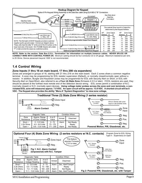
Data Bus Cable<br />
CAT5 or CAT6 Recommended<br />
To Red (Pos) Wire<br />
To Brown Wire<br />
NOTE: The first batch of M1KP Keypads provided a switched<br />
negative (pull to ground) output. Connect per diagram above.<br />
These units have the letter "E" at the end of the ID number on the<br />
lower back side of the board. EG: PC096E Boards with a letter<br />
"F" or later provide the output as a switched positive.<br />
+<br />
-<br />
Hookup Diagram for Keypad<br />
Splice 6 Pin Keypad Wiring Assembly to the Data Bus cable using ELK-900-2 "B" Connectors.<br />
Load (50mA max)<br />
i.e. Relay, LED<br />
BLACK<br />
WHITE<br />
GREEN<br />
RED<br />
BLUE<br />
BROWN<br />
Keypad<br />
Wiring<br />
Assembly<br />
1<br />
6<br />
To BROWN Wire<br />
To BLACK (Neg) Wire<br />
+<br />
-<br />
ELK-M1KP<br />
Keypad 1<br />
Load (50mA max)<br />
I.E. LED, Relay<br />
Optional programmable Output from Keypad<br />
To BLUE Wire<br />
2200<br />
N.C. N.O. Ohm<br />
To BLACK (Neg) Wire<br />
EOL<br />
Optional programmable Zone Input from Keypad<br />
See Note about<br />
Data Bus<br />
Termination<br />
The optional Zone Input # or Output # is<br />
determined by the Keypad Address.<br />
KP Zone Output<br />
Address # #<br />
1 193 193<br />
2 194 194<br />
3 195 195<br />
4 196 196<br />
5 197 197<br />
6 198 198<br />
7 199 199<br />
8 200 200<br />
KP Zone Output<br />
Address # #<br />
9 201 201<br />
10 202 202<br />
11 203 203<br />
12 204 204<br />
13 205 205<br />
14 206 206<br />
15 207 207<br />
16 208 208<br />
NOTE: Refer to the section ‘Data Bus E.O.L. Termination’ for information on multiple homerun cables. NEVER SPLICE OR<br />
CONNECT WIRE WITH CONTROL POWER ON. Minimum cabling should be four conductor 22 or 24 gauge. Maximum resistance per wire<br />
is 25 Ohms. Device placement beyond 1000' is not recommended.<br />
1.4 Control Wiring<br />
Zone Inputs (1 thru 16 on main board, 17 thru 208 via expanders)<br />
Zones are arranged in groups of 16, starting with Z1 thru Z16 on the main board. Each 2 zones share a common negative<br />
terminal. A zone may be programming for EOL resistor supervision (Default), or normally closed/normally open without a<br />
resistor. In addition, Burglar and Keyswitch zones may be programmed for EOL with Security Alert on Short, or EOL with<br />
Security Alert on Open/Short, also referred to as a Four (4) State Zone (firmware 4.3.5 or later). If EOL resistors are used, they<br />
should be placed at the furthest most remote end of the detection device wiring. EOL zones permit a combination of N.C.<br />
(normally closed) or N.O. (normally open) devices. Using voltage meter probes across the zone and com terminals, a nonviolated<br />
EOL zone will measures approx. 7.0 VDC. An open circuit will be approx. 13.8 VDC. A shorted circuit will be 0<br />
VDC. The Keypad also provides the ability “Menu 8 “System Diagnostics” to view zone voltage.<br />
Traditional Three (3) State Zone Wiring (1 series resistor)<br />
2200<br />
Ohm<br />
EOL<br />
N.C.<br />
Alarm<br />
Contact<br />
Zone<br />
Resistance<br />
Short ~<br />
2.2k Ohms<br />
Open ~<br />
N.O.<br />
Contact<br />
Alarm Contact<br />
Diagostic Table<br />
Approx. Range<br />
of Zone Voltage<br />
0 - 3.9 Volts<br />
4.0 - 8.8 Volts<br />
8.9 - 13.8 Volts<br />
A to D<br />
Value<br />
0 - 72<br />
73 - 170<br />
171 - 255<br />
Zone Input<br />
Neg.<br />
Armed<br />
Alarm<br />
-<br />
Alarm<br />
Condition When:<br />
Disarmed<br />
Not Ready<br />
Ready<br />
Not Ready<br />
N.C. Tamper<br />
Contacts<br />
N.C. Alarm<br />
Contacts<br />
2200 Ohm<br />
EOL Resistor<br />
Wire in Series with zone<br />
input or use another zone.<br />
Zone<br />
Input<br />
Neg.<br />
Pos.<br />
Neg.<br />
Powered Motion, PIR, Glassbreak, etc.<br />
Optional Four (4) State Zone Wiring (2 series resistors w/ N.C. contacts)<br />
2200<br />
Ohm<br />
EOL<br />
Tamper Contact<br />
N.C.<br />
Zone<br />
Resistance<br />
Short ~<br />
2.2k Ohms<br />
4.4k Ohms<br />
Open ~<br />
N.C.<br />
Alarm<br />
Contact<br />
2200 Ohm<br />
Resistor<br />
Diagnostic Table<br />
Approx. Zone<br />
Voltage Reading<br />
0 - 3.9 Volts<br />
4.0 - 7.3 Volts<br />
7.4 - 11 Volts<br />
11.1 - 13.8 Volts<br />
N.O.<br />
Contact<br />
A to D<br />
Value<br />
0 - 72<br />
73 - 159<br />
160 - 220<br />
221 - 255<br />
Zone Input<br />
Neg.<br />
Fig 1: N.C. Alarm Contact<br />
(Unpowered) with N.C. Tamper<br />
Armed<br />
Alarm<br />
-<br />
Alarm<br />
Alarm<br />
Condition When:<br />
This feature<br />
requires Firmware<br />
2.3.5 or later.<br />
Disarmed<br />
Sec. Alert/Tamper<br />
Ready<br />
Not Ready<br />
Sec. Alert/Tamper<br />
N.C. Tamper<br />
Contacts<br />
N.C. Alarm<br />
Contacts<br />
Program Zone for EOL Wiring<br />
Type 4 - Supervisory on Open<br />
2200 Ohm<br />
EOL Resistor<br />
2200 Ohm<br />
Resistor<br />
M1G Installation and Programming Page 9<br />
Zone<br />
Input<br />
Neg.<br />
Pos.<br />
Neg.<br />
Fig 2: Powered PIR, Glassbreak, etc. with Tamper


