

INSTALLATION MANUAL - Smarthome
INSTALLATION MANUAL - Smarthome
INSTALLATION MANUAL - Smarthome

You also want an ePaper? Increase the reach of your titles
YUMPU automatically turns print PDFs into web optimized ePapers that Google loves.
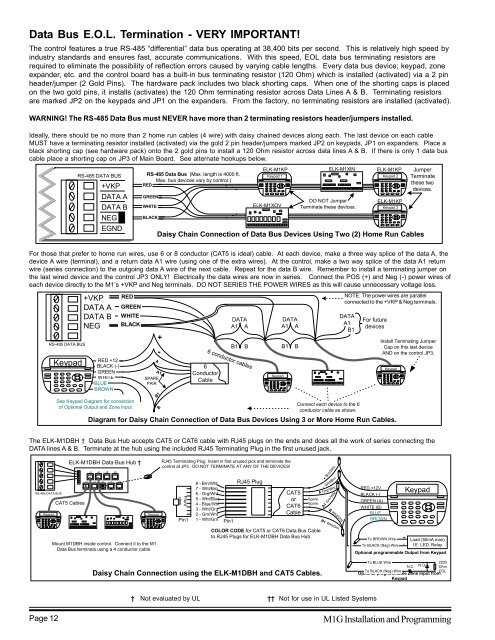
Data Bus E.O.L. Termination - VERY IMPORTANT!<br />
The control features a true RS-485 “differential” data bus operating at 38,400 bits per second. This is relatively high speed by<br />
industry standards and ensures fast, accurate communications. With this speed, EOL data bus terminating resistors are<br />
required to eliminate the possibility of reflection errors caused by varying cable lengths. Every data bus device; keypad, zone<br />
expander, etc. and the control board has a built-in bus terminating resistor (120 Ohm) which is installed (activated) via a 2 pin<br />
header/jumper (2 Gold Pins). The hardware pack includes two black shorting caps. When one of the shorting caps is placed<br />
on the two gold pins, it installs (activates) the 120 Ohm terminating resistor across Data Lines A & B. Terminating resistors<br />
are marked JP2 on the keypads and JP1 on the expanders. From the factory, no terminating resistors are installed (activated).<br />
WARNING! The RS-485 Data Bus must NEVER have more than 2 terminating resistors header/jumpers installed.<br />
Ideally, there should be no more than 2 home run cables (4 wire) with daisy chained devices along each. The last device on each cable<br />
MUST have a terminating resistor installed (activated) via the gold 2 pin header/jumpers marked JP2 on keypads, JP1 on expanders. Place a<br />
black shorting cap (see hardware pack) onto the 2 gold pins to install a 120 Ohm resistor across data lines A & B. If there is only 1 data bus<br />
cable place a shorting cap on JP3 of Main Board. See alternate hookups below.<br />
RS-485 DATA BUS<br />
+VKP<br />
DATA A<br />
DATA B<br />
NEG<br />
EGND<br />
RS-485 Data Bus (Max. length is 4000 ft.<br />
Max. bus devices vary by control.)<br />
RED<br />
GREEN<br />
WHITE<br />
BLACK<br />
ELK-M1KP<br />
Keypad 1<br />
ELK-M1XOV<br />
ELK-M1XIN<br />
DO NOT Jumper<br />
Terminate these devices.<br />
ELK-M1KP<br />
Keypad 2<br />
ELK-M1KP<br />
Keypad 3<br />
Jumper<br />
Terminate<br />
these two<br />
devices.<br />
Daisy Chain Connection of Data Bus Devices Using Two (2) Home Run Cables<br />
For those that prefer to home run wires, use 6 or 8 conductor (CAT5 is ideal) cable. At each device, make a three way splice of the data A, the<br />
device A wire (terminal), and a return data A1 wire (using one of the extra wires). At the control, make a two way splice of the data A1 return<br />
wire (series connection) to the outgoing data A wire of the next cable. Repeat for the data B wire. Remember to install a terminating jumper on<br />
the last wired device and the control JP3 ONLY! Electrically the data wires are now in series. Connect the POS (+) and Neg (-) power wires of<br />
each device directly to the M1’s +VKP and Neg terminals. DO NOT SERIES THE POWER WIRES as this will cause unnecessary voltage loss.<br />
RS-485 DATA BUS<br />
Keypad<br />
+VKP<br />
DATA A<br />
DATA B<br />
NEG<br />
RED +12<br />
BLACK (-)<br />
GREEN<br />
WHITE<br />
BLUE<br />
BROWN<br />
RED<br />
GREEN<br />
WHITE<br />
BLACK<br />
A<br />
SPARE<br />
PAIR<br />
B1<br />
+<br />
-<br />
A1<br />
6<br />
Conductor<br />
Cable<br />
DATA<br />
A1 A<br />
B1<br />
B<br />
6 conductor cables<br />
Keypad<br />
DATA<br />
A1 A<br />
B1<br />
B<br />
NOTE: The power wires are parallel<br />
connected to the +VKP & Neg terminals.<br />
DATA<br />
A1<br />
B1<br />
For future<br />
devices<br />
Install Teminating Jumper<br />
Cap on this last device<br />
AND on the control JP3.<br />
Keypad<br />
See Keypad Diagram for connection<br />
of Optional Output and Zone Input<br />
B<br />
Connect each device to the 6<br />
conductor cable as shown.<br />
Diagram for Daisy Chain Connection of Data Bus Devices Using 3 or More Home Run Cables.<br />
The ELK-M1DBH † Data Bus Hub accepts CAT5 or CAT6 cable with RJ45 plugs on the ends and does all the work of series connecting the<br />
DATA lines A & B. Terminate at the hub using the included RJ45 Terminating Plug in the first unused jack.<br />
RS-485 DATA BUS<br />
Keypad<br />
ELK-M1DBH Data Bus Hub †<br />
CAT5 Cables<br />
J2 J4 J6 J8<br />
J1 J3 J5 J7 J9<br />
Keypad<br />
Mount M1DBH inside control. Connect it to the M1<br />
Data Bus terminals using a 4 conductor cable.<br />
RJ45 Terminating Plug Insert in first unused jack and terminate the<br />
control at JP3. DO NOT TERMINATE AT ANY OF THE DEVICES!<br />
Front<br />
view<br />
Pin1<br />
8 - Brn/Wht<br />
7 - Wht/Brn<br />
6 - Org/Wht<br />
5 - Wht/Blue<br />
4 - Blue/Wht<br />
3 - Wht/Org<br />
2 - Grn/Wht<br />
1 - Wht/Grn<br />
Daisy Chain Connection using the ELK-M1DBH and CAT5 Cables.<br />
Pin1<br />
RJ45 Plug<br />
CAT5<br />
or<br />
CAT6<br />
Cable<br />
Spare<br />
Spare<br />
COLOR CODE for CAT5 or CAT6 Data Bus Cable<br />
to RJ45 Plugs for ELK-M1DBH Data Bus Hub.<br />
+ Brn/Wht<br />
- Wht/Brn<br />
A Org/Wht<br />
A1 Grn/Wht<br />
B Wht/Org<br />
B1 Wht/Grn<br />
RED +12V<br />
BLACK (-)<br />
GREEN (A)<br />
WHITE (B)<br />
BLUE<br />
BROWN<br />
Keypad<br />
To BROWN Wire + Load (50mA max)<br />
To BLACK (Neg) Wire - I.E. LED, Relay<br />
Optional programmable Output from Keypad<br />
To BLUE Wire<br />
2200<br />
N.C N.O Ohm<br />
To BLACK (Neg) Wire . . EOL<br />
Optional programmable Zone Input from<br />
Keypad<br />
† Not evaluated by UL †† Not for use in UL Listed Systems<br />
Page 12<br />
M1G Installation and Programming


