Special Issue; Products for Industrial Machinery - NTN
Special Issue; Products for Industrial Machinery - NTN
Special Issue; Products for Industrial Machinery - NTN

You also want an ePaper? Increase the reach of your titles
YUMPU automatically turns print PDFs into web optimized ePapers that Google loves.
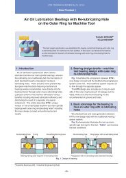
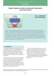
Development of Aerostatic Bearing Spindle <strong>for</strong> Precision Machine Tools<br />
Journal bearings<br />
Thrust bearings<br />
AC servo motor<br />
Rotary encoder<br />
Rotary shaft<br />
Non-contact seal<br />
<strong>for</strong> vacuum chuck<br />
Thrust plate<br />
Fig. 1 Structure of air spindle<br />
3. Specifications of Prototype Spindle<br />
The specifications (target values) <strong>for</strong> <strong>NTN</strong>’s<br />
prototype aerostatic bearing spindle <strong>for</strong> machine tools<br />
are summarized in Table 1.<br />
Previously, the maximum running speed with this<br />
type of spindle was approximately 10,000 r/min. In<br />
contrast, the maximum targeted running speed with<br />
<strong>NTN</strong>’s spindle is 20,000 r/min. To ensure good<br />
machining accuracy, it has been determined that it<br />
should have an NRRO (non-repetitive run-out)<br />
comparable to that of an aerostatic spindle <strong>for</strong><br />
inspection devices and the axial displacement of the<br />
chuck face during steady running of the spindle should<br />
be limited to 1 m or smaller.<br />
Max. running speed<br />
Air feed pressure to bearing<br />
Radial rigidity<br />
Axial rigidity<br />
NRRO<br />
Radial<br />
Axial<br />
Displacement on chuck face<br />
Table 1 Specifications<br />
20,000 rmin<br />
0.49 MPa<br />
45 N/m<br />
227 N/m<br />
0.010m or less<br />
0.010m or less<br />
1m or less during steady running<br />
4. Structure of the Aerostatic Spindle<br />
<strong>for</strong> Machine Tools<br />
1) Realization of greater rigidity and higher accuracy<br />
The structure of the authors’ aerostatic bearing<br />
spindle is illustrated in Fig. 2. A total of four journal<br />
bearings are placed in the front and rear sides of the<br />
thrust bearings to enhance the rigidity of the aerostatic<br />
bearing spindle. Furthermore, seeking higher<br />
accuracy, the layout <strong>for</strong> the air feed holes on the<br />
journal bearings have been optimized in order to<br />
inhibit high order vibration that would otherwise occur<br />
due to the interaction between the <strong>for</strong>m errors on the<br />
rotary shaft and the layout of the air feed holes, as<br />
well as to improve the dynamic rigidity of the bearings.<br />
2) Realization of higher torque<br />
To attain both a higher torque on the driving section<br />
and a smaller spindle outside diameter, two motors<br />
are coupled in tandem, thereby the authors’ aerostatic<br />
bearing spindle features a torque twice as high<br />
compared to ordinary aerostatic bearing spindle<br />
designs.<br />
3) Control of chips and coolant<br />
For the vacuum chuck mechanism that secures<br />
workpieces, to prevent the coolant entering the chuck<br />
from reaching the bearing section, the suction holes<br />
are situated further apart from the bearings compared<br />
to conventional aerostatic bearing spindle<br />
arrangements. To avoid ingress of chips and coolant<br />
into the bearings, a non-contact air-seal has been<br />
incorporated and a narrow gap is provided between<br />
the rotary shaft and the fixed section (housing),<br />
thereby compressed air is allowed to gush out through<br />
this gap to prevent chips and coolant from reaching<br />
the bearings.<br />
4) Control of heat buildup<br />
Aerostatic bearings are known to generate less<br />
heat. However, when any aerostatic bearing is run at<br />
a higher speed, the heat buildup resulting from the<br />
shearing of gaseous matter in the bearing clearance<br />
cannot be ignored. In addition, the magnitude of heat<br />
generated from the motor arrangement of <strong>NTN</strong>’s<br />
prototype spindle was expected to be greater than that<br />
of similar conventional arrangements. To solve this<br />
-35-
![[New Product] Unit Products for Office Equipment - NTN](https://img.yumpu.com/27154451/1/184x260/new-product-unit-products-for-office-equipment-ntn.jpg?quality=85)
![[New Product] Development of Oil-impregnated Sintered ... - NTN](https://img.yumpu.com/27154427/1/184x260/new-product-development-of-oil-impregnated-sintered-ntn.jpg?quality=85)