WP6-Brochure-E4 brochure - ELA European Lift Association.
WP6-Brochure-E4 brochure - ELA European Lift Association.
WP6-Brochure-E4 brochure - ELA European Lift Association.

You also want an ePaper? Increase the reach of your titles
YUMPU automatically turns print PDFs into web optimized ePapers that Google loves.
traction or hydraulic, required a machine room where the motor – and pump, in the case of<br />
hydraulic lifts – and a control cabinet were stored (see figures 2‐3 and 2‐4) due to the size of<br />
the equipment. This machine room was typically located above the lift shaft for traction lifts<br />
(or below for hydraulic lifts).<br />
Evolution in permanent magnet motor technology (see p. 23) and motor drives (see p. 17)<br />
allowed a significant reduction in the size and shape of these components which, in turn, made<br />
it possible to fit all the equipment directly into the lift shaft (these lifts are normally equipped<br />
with high efficiency gearless permanent magnet motors).<br />
Also, the size of the motor is reduced by the roping system used (see pp. 33). The ends of the<br />
cables are fixed to the supporting structure, and suspension sheaves are provided above (or<br />
below) the car and counterweight creating a force‐multiplying, compound pulley system.<br />
With 2:1 or 4:1 roping, car speed is reduced to 1/2 or 1/4, respectively, of the rope speed, and<br />
the load on the rope is reduced to 1/2 or 1/4 as well, hence the diameter and number of ropes<br />
can be reduced and a smaller motor can be used.<br />
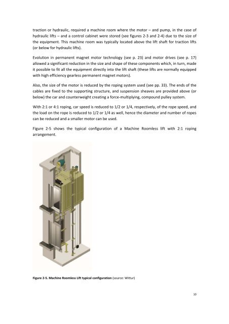
Figure 2‐5 shows the typical configuration of a Machine Roomless lift with 2:1 roping<br />
arrangement.<br />
Figure 2‐5. Machine Roomless <strong>Lift</strong> typical configuration (source: Wittur)<br />
10